Trill configuration example, Network requirements, Configuration procedure – H3C Technologies H3C S6300 Series Switches User Manual
Page 24
17
Task Command
Clear dynamic running statistics of
the TRILL process.
reset trill
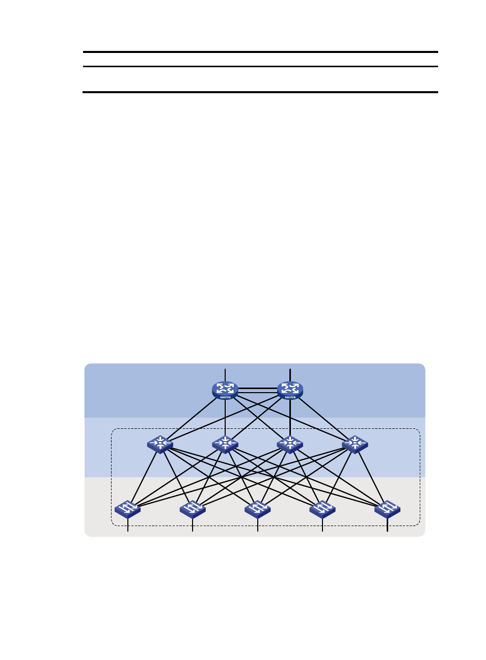
TRILL configuration example
Network requirements
As shown in
, configure TRILL in the Layer 2 data center network as follows:
•
Enable TRILL on the downlink ports of access layer devices to connect terminal devices to the TRILL
network.
•
Enable TRILL on the uplink ports of access layer devices, and configure these uplink ports as trunk
ports to pass TRILL frames to the TRILL network.
•
Enable TRILL on the downlink ports of distribution layer devices, and configure these downlink ports
as trunk ports to forward TRILL data frames.
•
Enable TRILL on the uplink ports of the distribution layer devices. These ports send the
de-encapsulated TRILL data frames to the core layer.
•
In the TRILL network, configure four TRILL distribution trees with RB 6 through RB 9 as the root bridges.
RB 6 through RB 9 are in descending priority order.
A hierarchical network has three layers (from up to down): the core layer, distribution layer, and access
layer. Usually, a port connecting to a higher layer device is called an uplink port, and a port connecting
to a lower layer device is called a downlink port.
Figure 7 Network diagram
Configuration procedure
This section provides only TRILL-related configurations.
Distribution layer
Access
layer
RB 6
RB 7
RB 8
RB 1
RB 2
RB 3
RB 4
RB 5
RB 9
Core layer
TRILL network