Figure 4 – Grass Valley 2040RDA-16FR User Manual
Page 14
14
2040RDA-FR/16FR — Instruction Manual
Installation
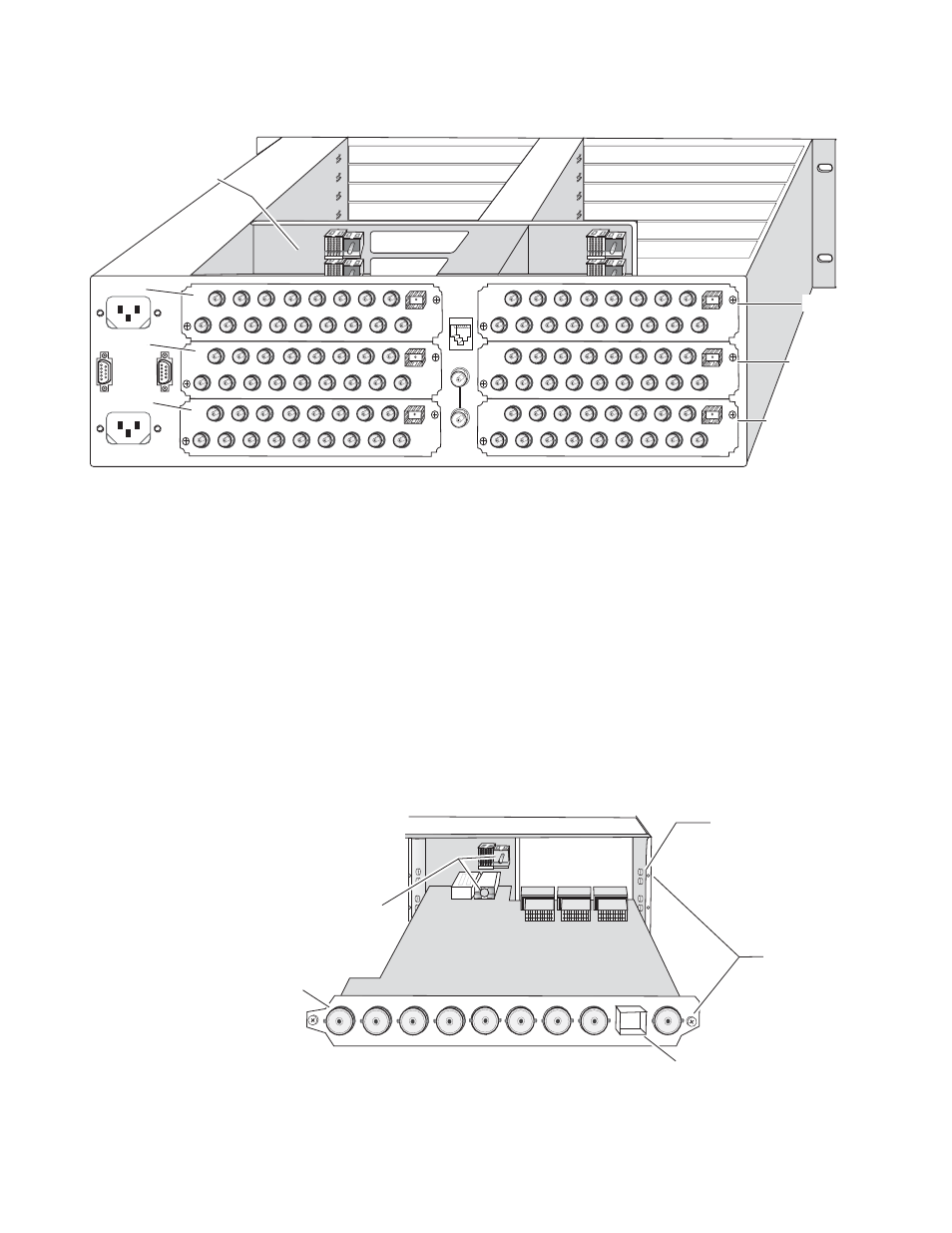
Figure 4. 2040RDA-16FR 3 RU Frame, Rear View
The 2040RDA-FR and 2040RDA-16FR front and rear modules and fiber
optic submodules can be plugged in and removed from a Kameleon 2000
Series frame with power on. When power is applied to the module, LED
indicators reflect the initialization process (see
To install a 2040RDA-FR module set in the frame:
1.
Locate a vacant slot in slot 1-12 in the rear of the 1 RU or 3 RU frame
(3 RU frame shown in
).
2.
Insert the rear module into a vacant rear slot in the frame as illustrated
in
Figure 5. Installing 2040RDA-FR Rear Module
Mid-frame motherboard
with power and
communication buses
Use rear media module slots 1, 3, and 5
Use rear media module slots 7, 9, and 11
8269_04
Slot 5
Slot 3
Slot 7
Slot 9
Slot 11
Slot 1
Alignment post
and receptacle
Screw locks
(both sides)
8360_11
2000 frame (rear view)
Board edge guides
(both sides)
2040RDA-FR-R Passive Rear Module
Fiber optic
connector cage
Input