Grass Valley 2040RDA-16FR User Manual
Page 15
2040RDA-FR/16FR — Instruction Manual
15
Installation
To install a 2040RDA-16FR module set in the frame:
1.
Locate a vacant slot in slot 1, 3, 5, 7, 9, or 11 of the rear of the 3 RU frame
(
). The rear module uses two slots.
2.
Insert the rear module into vacant rear slot 1, 3, 5, 7, 9, or 11 of the frame
as illustrated in
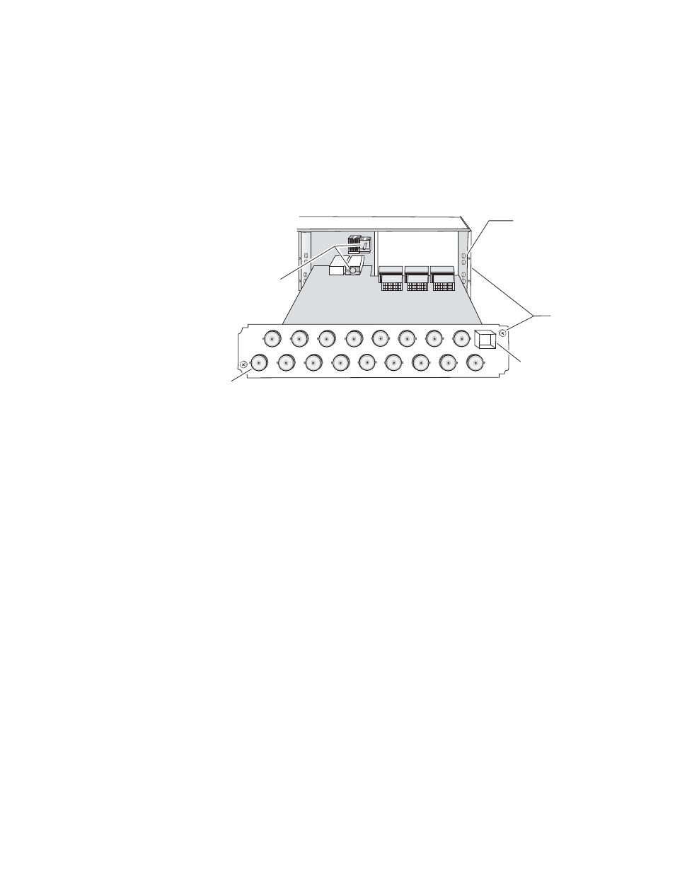
Figure 6. Installing 2040RDA-16FR Rear Module
To continue installation of 2040RDA-FR and 2040RDA-16FR modules set in
the frame:
1.
Verify that the module connector seats properly against the midplane.
2.
Using a crossblade screwdriver, tighten the two screw locks to secure
the module in the frame.
3.
To install the optional SFP submodule in the 2040RDA-FR, refer to
. The SFP submodule is hot-pluggable and may be installed or
removed with power applied to the module.
4.
To install the optional SFP submodule in the 2040RDA-16FR, refer to
. The SFP submodule is hot-pluggable and may be installed or
removed with power applied to the module.
The module type is identified by name on the label or can be identified
by the direction of the two arrow indicators on the label.
Note
Installing or removing the optical submodule while the module is powered up
will reset the module to a default state—that of the jumper settings currently
set for JP2, JP3, and JP4 (see
5.
With the handle in the up position, slide the metal casing, label side up,
into the cage connector on the top right of the rear module.
Note
When installed properly, the front end of the submodule will line up with the
BNCs. Do not try to force it in further.
Alignment post
and receptacle
Screw locks
(both sides)
8269_03
2000 frame (rear view)
Board edge guides
(both sides)
2040RDA-16FR-R Passive Rear Module
Fiber optic
connector cage
Input