Outputs, Delay input, Power up – Grass Valley 8916 User Manual
Page 11: Operation indicator leds, Ocess (see
8916 Instruction Manual
5
Power Up
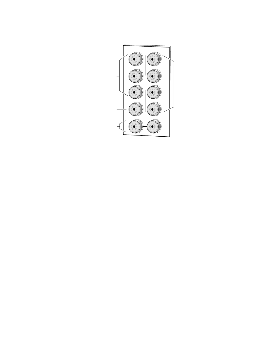
Figure 3.
8916
Input/Output Connectors
Outputs
The 8916 has seven AES/EBU serial digital output connectors—J1 through
J6, and J8. The destination equipment should have a 75
Ω
input impedance
or loop through inputs that are terminated into 75
Ω
.
Delay Input
A delay signal input BNC (J7) is provided for a reference signal from a
Grass Valley video sync generator (see Note
).
Power Up
The various front LED indicators and configuration switches are illustrated
in
. Upon power-up, the green PWR LED should light and the
yellow CONF LED should illuminate for the duration of module initializa-
tion.
Operation Indicator LEDs
With factory default configuration and a valid input signal connected, the
green PWR LED, the yellow TRACK, and one of the green signal rate LEDs
should illuminate (refer to
to see the possible operating
indicator combinations).
Audio input presence is indicated by the 32 kHz, 44.1 kHz, or 48 kHz LED
(indicating the module has locked to the indicated signal rate).
J2
J4
J6
J8
J9 J10
IN
AES/EBU
Outputs
DAx
O
U
T
J3
J5
J7
J2
J1
J6
J8
0585-02
AES/EBU
Loopthrough Input
Delay Input
from Frame Sync
AES/EBUOutputs