Module placement in the 8900 frame – Grass Valley 8916 User Manual
Page 9
8916 Instruction Manual
3
Installation
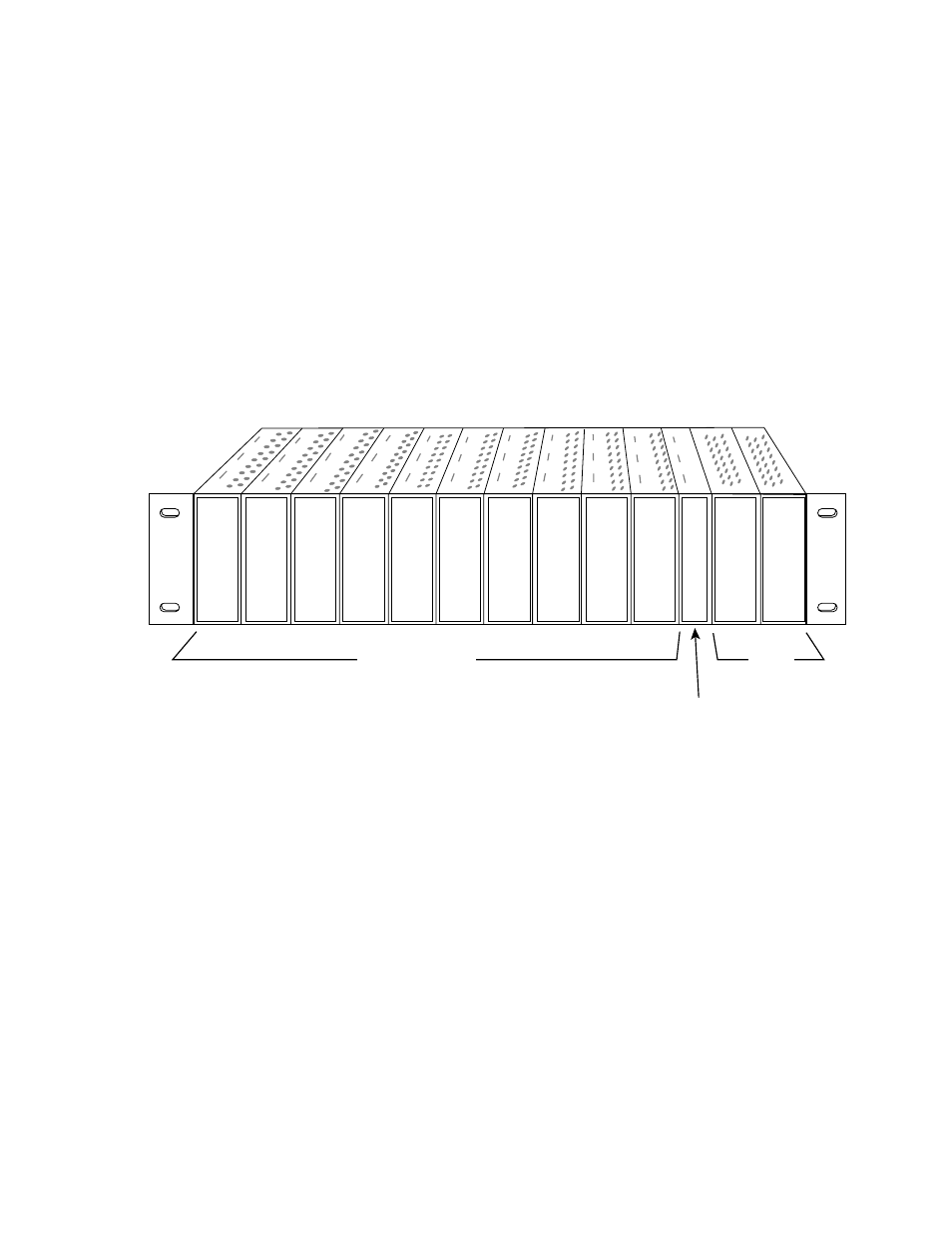
Module Placement in the 8900 Frame
There are ten slot locations in the frame to accommodate either analog or
digital modules. These are the left ten locations. Refer to
The two slots on the right are allocated for the power supplies. For addi-
tional information concerning the Power Supply module, refer to the 8900
Power Supply manual.
The third slot from the right is allocated for the Controller module. This
module provides an interface for the SMPTE 269M fault reporting (health
alarm). For additional information concerning the Controller module, refer
to the 8900 Controller manual.
Figure 1. 8900 Series Frame
8900 modules are interchangeable within the module slots. There are 10
BNC connectors in each slot’s I/O group. The functional assignment of
each connector in a group is determined by the module that is placed in
that slot. The maximum number of modules an 8900 frame can accept is
ten.
illustrates the rear connectors for an 8900 Series frame.
Controller
Module
(only)
Any 8900 Module
Power
Supplies
(only)
0614-03