Figure 4, Upon power – Grass Valley 8916 User Manual
Page 12
6
8916 Instruction Manual
8916 AES/EBU Auto-Tracking Delay DA
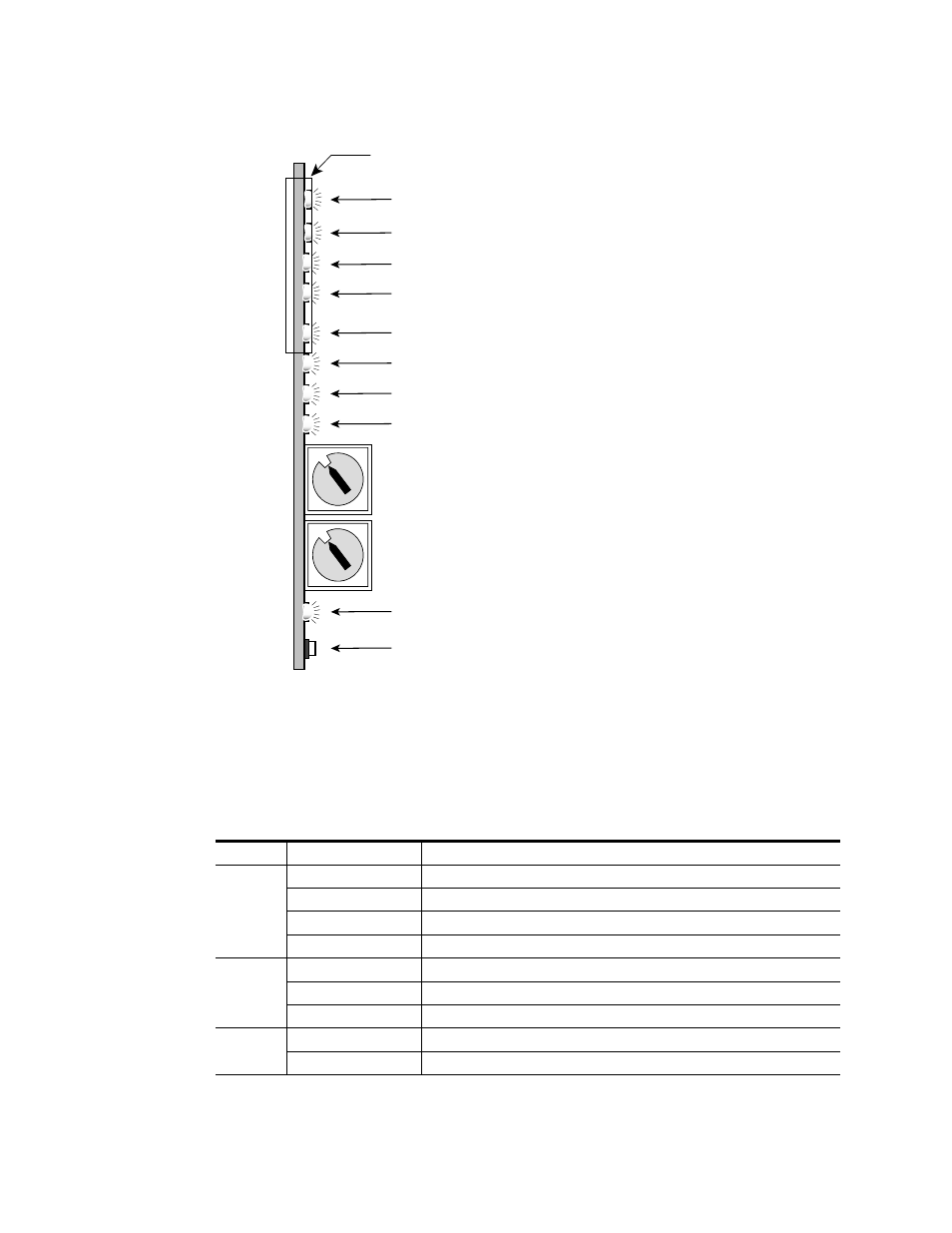
Figure 4. LEDs and Configuration Switches
A red FAULT LED indicates an error situation and, with the previously
described LEDs, can indicate the operational conditions presented in
. The table describes signal output and LED indications for various
input/reference combinations and user settings.
Table 2. Indicator LEDs and Conditions Indicated
LED
Indication
Condition
Fault
(red)
Off
Normal operation
On continuously
Module has detected internal fault
Long flash
Configuration problem: Check inputs and settings
Short flash
CRC (cyclic redundancy check) error detected
COMM
(yellow)
Off
No activity on frame communication bus
Long flash
Location Command received by the module from a remote control system
Short flash
Activity present on the frame communication bus
CONF
(yellow)
Off
Module is in normal operating mode
On continuously
Module is initializing, changing operating modes or updating firmware
Coarse Delay Adjust
Rotary switch
32 kHz – Green LED on indicates lock to a 32 kHz signal
PWR – Green diagnostic LED on indicates power OK
FAULT – Red diagnostic LED is off during normal operation
Ejector Tab
COMM – Yellow LED on during remote control communication
CONF – Yellow LED on when module is initializing or
processing control data
44.1 kHz – Green LED on indicates lock to a 44.1 kHz signal
48 kHz – Green LED on indicates lock to a 48 kHz signal
TRACK – Green LED on indicates auto delay is being added to the fixed delay
GND
REMOTE OVR – Yellow LED on indicates local switches and
jumper settings are overridden by remote control
0585_06
0
1
2
3 4
5 6 7
8
9
A
B
CD
E
F
Fine Delay Adjust
Rotary switch
0
1
2
3 4
5 6 7
8
9
A
B
CD
E
F