Configuration switches s1 and s2, Refer to, Table 1 – Grass Valley 8945EDA v.1.3.0 User Manual
Page 14
14
8945EDA/-D — Instruction Manual
Installation
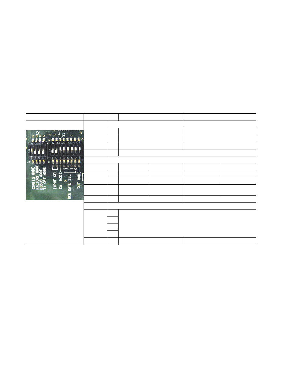
Configuration Switches S1 and S2
gives the parameters set with the onboard switches S1 and S2 on the
8945EDA and 8945EDA-D module circuit boards. Parameters may also be
set using the web page or Newton Control panel controls when the
8900NET (Net Card) module is installed in the GeckoFlex frame. Refer to
the Configuration Summary table,
, for a complete list of
defaults and parameters for each control type.
Note
Remote control settings made with the web interface will override local set-
tings. To lock out remote control, set the Config Mode to Off (LOCAL).
Table 1. Switch S1 and S2 Settings
Switches S1 and S2
Function
Pin
0 (Left/Off)
1 (Right/On)
Switch S2
Config Mode
1
LOCAL (Remote control locked out)
LCL&REM (Local and Remote)
Factory Mode
2
Off
Factory use only
Test Mode
3
Off
Factory use only
Tx Opt Mode
4
Not used on the 8945EDA/-D
Switch S1
Input Select
Coax In 1 J9
Coax In 2 J10
Coax In 1 J9 (single)
Coax In 2 J10 (single)
1
0
1
1
0
2
0
1
0
1
Coax Outputs
J1, J3, J5, J7
J2, J4, J6, J8
J1, J2, J3, J4,
J5, J6, J7, J8
J1, J2, J3, J4,
J5, J6, J7, J8
Eq. Mode
3
Bypass
Active
Rck Rate Sel (Reclocking rate selection)
4
Not used on the 8945EDA/-D
5
6
7
Out Mode
8
SD/ASI
HD