Grass Valley 8945EDA v.1.3.0 User Manual
Page 19
8945EDA/-D — Instruction Manual
19
Power Up
A red FAULT LED indicates an error situation and, when noted with the
other indicator LEDs, can indicate a specific problem area.
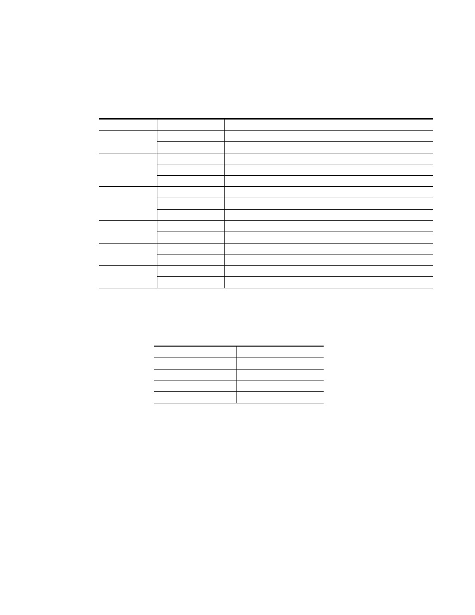
describes
signal output and LED indications for the various input/reference combi-
nations.
provides the possible input and output conditions that result from
different input signals and conditions.
Table 3. Indicator LEDs and Conditions Indicated
LED
Indication
Condition
FAULT
(red)
Off Normal
operation
On continuously
Module has detected internal fault
COMM
(yellow)
Off
No activity on frame communication bus
Long flash
Location Command received by the module from a remote control system
Short flash
Activity present on the frame communication bus
CONFIG
(yellow)
Off
Module is in normal operating mode
On continuously
Module is initializing, changing operating modes or updating firmware
Long flash
Location command received by the module from a remote control system
PWR
(green)
Off
No power to module or module’s DC/DC converter failed
On continuously
Normal operation, module is powered
PRES COAX IN
(green)
Off
Indicates no signal present on the coax input
On continuously
Indicates signal present on the coax input
BYPASS
(yellow)
Off
No bypass of the equalizer
On continuously
Bypass of the equalizer
Table 4. Input and Output Conditions
Input Condition
Output Condition
Serial Digital Component (SDI)
Serial Digital Component (SDI)
HD Digital Component (SDI)
HD Digital Component (SDI)
Other carrier
Other carrier
No input
Passing