Control cabling, Ethernet cabling – Grass Valley Acappella v.3.2.4 User Manual
Page 42
42
Acappella — Instruction Manual
Section 2 — Installation
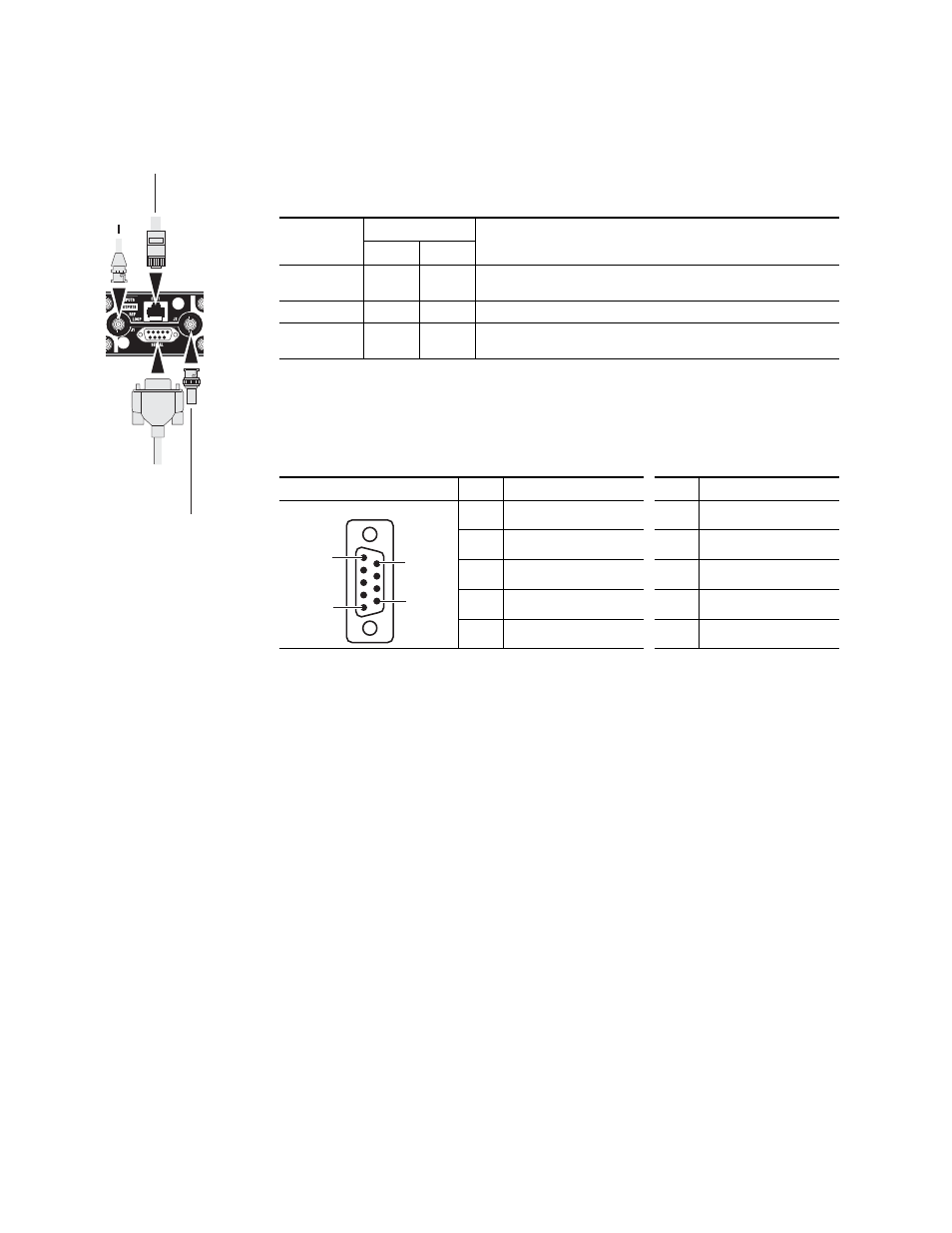
Control Cabling
shows the connectors in the Control area of the Acappella frame.
Serial 9 Pin D Connector Pinout
contains pinout information for the Serial RS-422 9 Pin D connector.
Note
Refer to the latest version of the Routing Products Protocols Manual for
information about the Terminal/Computer Interface (T/CI) Protocol used to
control Acappella systems. This manual is available for download on the
Grass Valley web site (see
).
Ethernet Cabling
The Acappella frame uses Ethernet to communicate. Use standard pin-to-
pin (patch) Category 5e cables if you are using switches between the
routers, panels, and PC. It is also possible to use a crossover cable to
connect an Acappella Router directly to either a Remote Panel or a PC; this
option is only practical in very small systems.
Network system with an Acappella router, a Remote Panel, and a PC con-
nected to a switch.
Table 4. Control Cabling
Label
Connector
Details
Type
Gender
ENET
RJ-45
Female
Ethernet network communication interface is 100Base-T compatible, use
Category 5e cable, 8 conductor twisted pair.
SERIAL
9 pin D
Female
RS-422 interface, use serial cable.
REF LOOP
BNC
Female
Video reference supports Color Black or Tri-Level-Sync, use unbalanced 75
ohm connector, Loop-thru cabling supported.
Table 5. Serial D Connector Pinouts
Controlled
Pin
Function
Pin
Function
1
GND
6
TX Com
2
TX-
7
TX+
3
RX+
8
RX-
4
RX Com
9
GND
5
NC
-
-
8300_00_38
Reference Loop
75 ohm Terminator
Ethernet
Serial
RS-422
Reference
Loop
5
6
9
1
9 Pin D Female