Amu indicators, Amu identifier, Video channel – Grass Valley Digital Wireless Triax Camera System User Manual
Page 18: Data channel, Lock, Error, Power
18
User’s Guide - Digital Wireless System
version 9
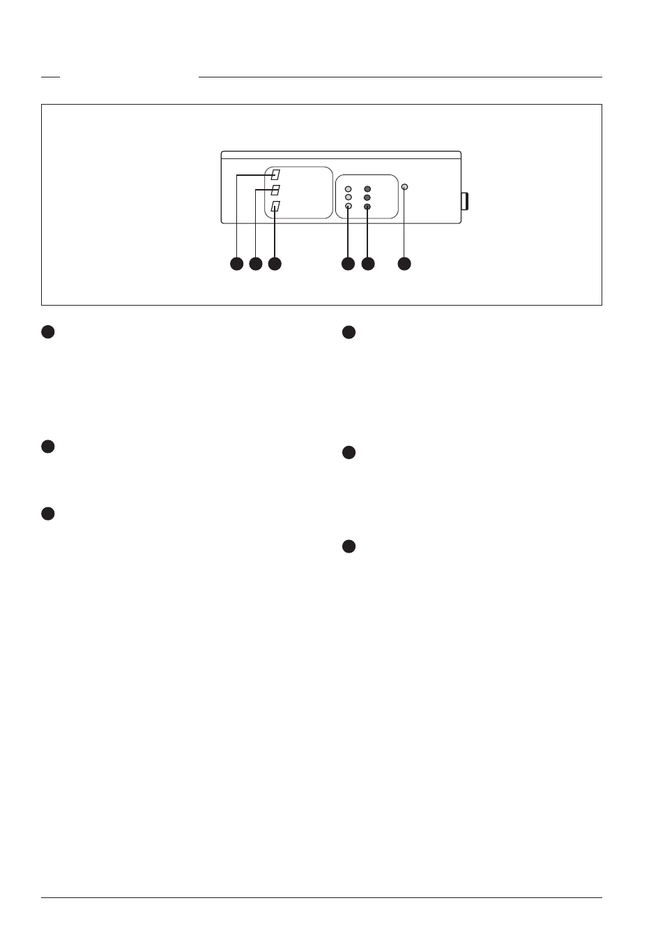
AMU IDENTIFIER
VIDEO CHANNEL
DATA CHANNEL
lock
error
ANT
1
2
3
POWER
AMU IDENTIFIER
The display shows the number of the AMU (to identify AMUs
when there are two AMUs in a system). This number also
appears in the viewfinder at the bottom right.
When the AMU automatically switches to long distance triax
mode the decimal dot in the display lights.
VIDEO CHANNEL
The display shows the channel number on which the wireless
video signal from the camera is transmitted (set on WCU).
DATA CHANNEL
The display shows the channel number on which the wireless
control signal to the camera is transmitted (set on WCU). A
dash (-) indicates that no data emitter is connected.
When the AMU detects that a 456 MHz Data Emitter is
connected, the decimal dot in the display lights.
1
2
LOCK
These three green indicators, whose numbers correspond
to the three transmission antennas, light to indicate that
there is a connection between camera and the specific
AMU antenna. At least one of these indicators must be lit
to have a connection. If all three are lit, then the RF link is
at its strongest.
ERROR
A red indicator lights to indicate a problem (uncorrectable
errors) in the connection between the camera and a specific
AMU antenna. The connection remains reliable as long as all
three indicators do not light at the same time.
POWER
This indicator lights when power from the WCU is supplied
to the AMU via the triax cable.
3
4
5
6
3
4
6
5
2
1
AMU indicators