Configuring ancillary data, Selecting the xg inside channel – Grass Valley iTX Output Server 2 v.2.6 User Manual
Page 39
33
iTX Output Server 2
Channel Configuration Guide
Configuring Ancillary Data
The ancillary data for a channel is configured from the Channel tab of the Output Server 2
user interface.
To configure ancillary data for an Output Server 2 channel:
1 Open the Output Server 2 user interface for the channel you want to configure, as
described in
Accessing the Output Server 2 User Interface
2 Go to Configuration > Channel tab.
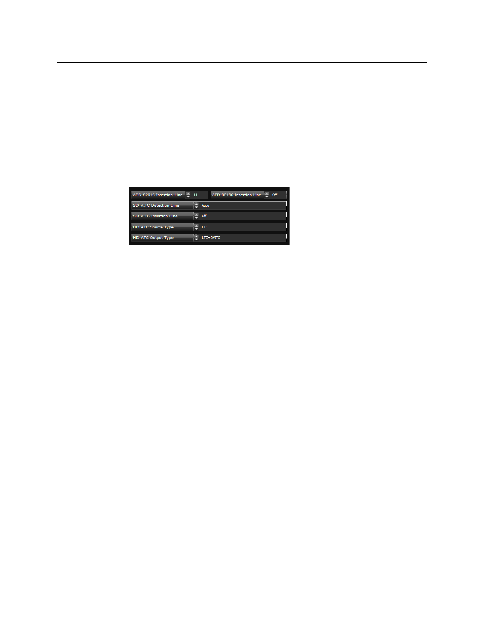
The channel configuration options appear. The ancillary data options are grouped
together on the middle left of the window.
3 The values for the Active Format Description (AFD) insertion lines are determined by
the selected Resolution. The default is typically the switch line +2 for all formats.
To change the default values, enter the new values into the following fields:
• AFD S2016 Insertion Line
• AFD RP186 Insertion Line.
4 If you are using a vertical interval timecode (VITC) generator for an SD channel,
complete the following fields, as required:
• SD VITC Detection Line
• SD VITC Insertion Line
5 To configure the ancillary timecode (ATC) data for a HD channel, select the required
options from the following drop-down lists:
• HD ATC Source Type
• HD ATC Output Type
6 Click Save to store your changes and automatically reboot the Output Server 2 service.
Alternatively, wait until you have finished making changes in other areas of the
Configuration panel, then click Save.
Selecting the XG Inside Channel
If you have an SDI I/O card that supports multiple channels and have extra channels
configured on the same playout server, you must specify which channel XG Inside is to use
for each instance of Output Server 2. This is done from the Channel tab of the Output
Server 2 user interface.
For more information about configuring Vertigo XG Inside, see the Vertigo XG Inside User
Guide.