About the camera link system components, T-pov 324 base unit – Grass Valley T-POV Bidirectional Robotic User Manual
Page 42
36
T-POV 324 Components
About the Camera Link System Components
About the Camera Link System Components
The T-POV 324 Robotic Camera Link Base Station and Camera Unit come in both portable
and rack mount configurations. In this chapter, the system components are described using
a single unit rack mounted base station with external 12 Volt power and a standard Mini-
Mussel Shell version of the Camera Unit also with external 12 Volt power.
The variations for the internally powered Base Station and the powered version of the
Camera Unit are described following the 12 Volt versions. Characteristics that are unique to
the two-link 12 Volt Base Stations are also described. The two link rack mounted Camera
Units operate similarly to the two link unit Base Stations.
•
•
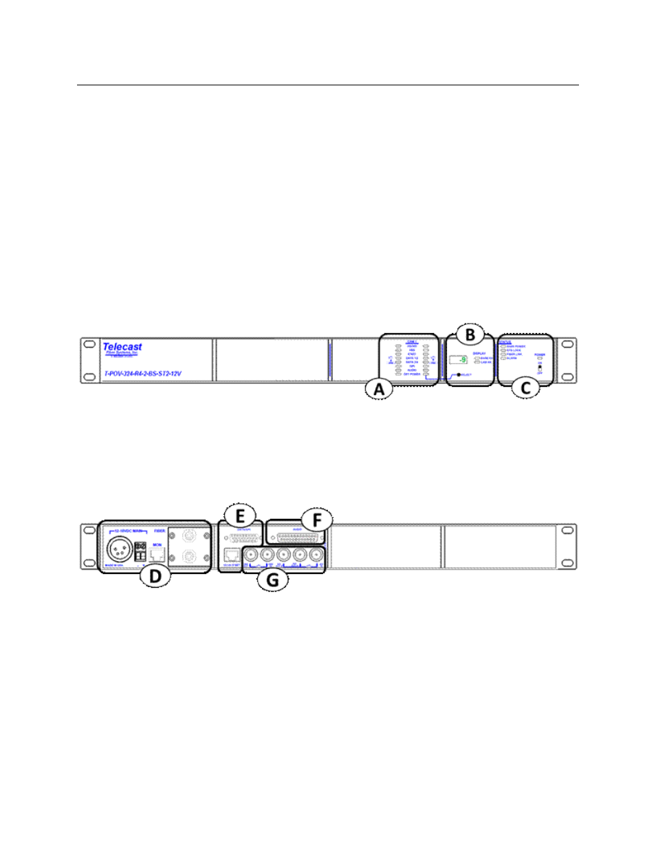
T-POV 324 Base Unit
Fig. 4-1: T-POV 324 Base Unit
The T-POV Base Station Front Panel has three features:
• A: Signal Indicator & Optical Power LEDs
• B: Signal Strength & System Setup Display
• C: Power/Status Indicators and Power Switch
Fig. 4-2: T-POV 324 Base Unit
The T-POV Base Station Connector Panel has four features:
• D: Power Section and Fiber Connector(s)
• E: Data/GPI-Tally/Ethernet Connectors
• F: Audio Multi-Pin Connector
• G: Video Connectors