Base station 12vdc terminal block wiring, Serial data configuration – Grass Valley T-POV Bidirectional Robotic User Manual
Page 87
81
Base Station 12VDC Terminal Block Wiring
Base Station 12VDC Terminal Block Wiring
Serial Data Configuration
For the Serial Data connector on the T-POV 301, the Data 2 channel is configurable. To
select between RS4222 and RS485 serial communication, select the proper settings on a
dual dip-switch contained on the main circuit board inside the unit. The switch is directly
behind the right side of the serial connectors on both the base station and the camera unit.
To configure the Serial Data connector
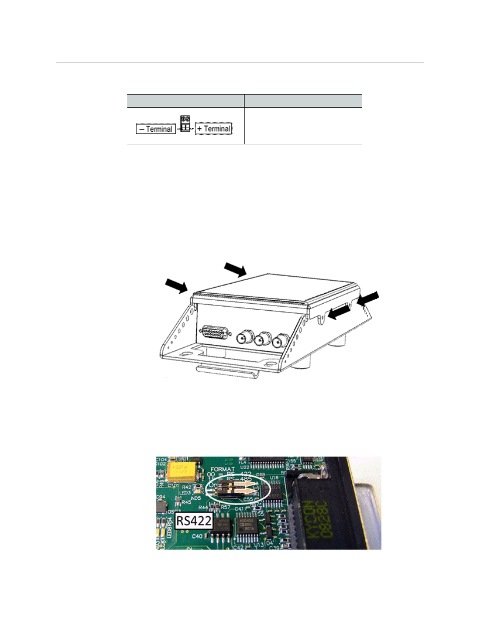
1 Remove the top of the unit by removing the four screws as shown. A Mini-Mussel Shell
Camera Unit is shown as an example.
Fig. A-1: Removing the top of the Camera Unit
2 Flip the dual dip-switch contained on the main circuit board inside the RS422 or R485
unit. For a multi-unit Base Station, you must set each unit separately and units can be
set differently from each other.
• For RS422 serial communications, slide both switches to the back of the unit
(towards the serial connector).
Fig. A-2: Flip switches on an RS422
Component
Description
Pin 1: Minus Voltage Terminal
Pin 2: Plus Voltage Terminal
This cable is end-user supplied.