HEIDENHAIN TNC 320 (340 55x-04) Cycle programming User Manual
Page 140
140
Fixed Cycles: Pocket Milling / Stud Milling / Slot Milling
5.4 SL
O
T
MILLING (Cy
c
le 253, DIN/ISO: G253)
U
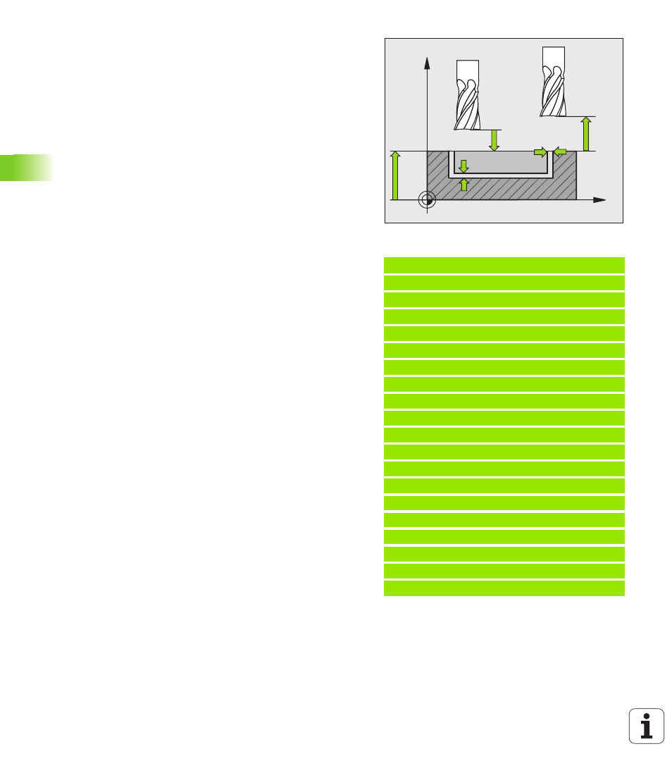
Setup clearance Q200 (incremental): Distance
between tool tip and workpiece surface. Input range
0 to 99999.9999
U
Workpiece surface coordinate Q203 (absolute):
Absolute coordinate of the workpiece surface. Input
range –99999.9999 to 99999.9999
U
2nd setup clearance Q204 (incremental): Coordinate
in the spindle axis at which no collision between tool
and workpiece (fixtures) can occur. Input range 0 to
99999.9999
U
Plunging strategy Q366: Type of plunging strategy:
0 = vertical plunging. The TNC plunges
perpendicularly, regardless of the plunging angle
ANGLE defined in the tool table.
1 = helical plunging. In the tool table, the plunging
angle ANGLE for the active tool must be defined as
not equal to 0. Otherwise, the TNC generates an
error message. Plunge on a helical path only if there
is enough space.
2 = reciprocating plunge. In the tool table, the
plunging angle ANGLE for the active tool must be
defined as not equal to 0. The TNC will otherwise
display an error message.
U
Feed rate for finishing Q385: Traversing speed of the
tool during side and floor finishing in mm/min. Input
range: 0 to 99999.9999; alternatively FAUTO, FU, FZ.
Example: NC blocks
8 CYCL DEF 253 SLOT MILLING
Q215=0
;MACHINING OPERATION
Q218=80
;SLOT LENGTH
Q219=12
;SLOT WIDTH
Q368=0.2
;ALLOWANCE FOR SIDE
Q374=+0
;ANGLE OF ROTATION
Q367=0
;SLOT POSITION
Q207=500
;FEED RATE FOR MILLING
Q351=+1
;CLIMB OR UP-CUT
Q201=-20
;DEPTH
Q202=5
;PLUNGING DEPTH
Q369=0.1
;ALLOWANCE FOR FLOOR
Q206=150
;FEED RATE FOR PLUNGING
Q338=5
;INFEED FOR FINISHING
Q200=2
;SETUP CLEARANCE
Q203=+0
;SURFACE COORDINATE
Q204=50
;2ND SETUP CLEARANCE
Q366=1
;PLUNGE
Q385=500
;FEED RATE FOR FINISHING
9 L X+50 Y+50 R0 FMAX M3 M99
X
Z
Q200
Q20
Q20
Q36
Q36