4 point tables, Application, Creating a point table – HEIDENHAIN TNC 320 (77185x-01) Cycle programming User Manual
Page 58: Point tables, Using fixed cycles 2.4 point tables
Using Fixed Cycles
2.4
Point tables
2
58
TNC 320 | User's Manual Cycle Programming | 3/2014
2.4
Point tables
Application
You should create a point table whenever you want to run a cycle,
or several cycles in sequence, on an irregular point pattern.
If you are using drilling cycles, the coordinates of the working
plane in the point table represent the hole centers. If you are
using milling cycles, the coordinates of the working plane in
the point table represent the starting-point coordinates of the
respective cycle (e.g. center-point coordinates of a circular pocket).
Coordinates in the spindle axis correspond to the coordinate of the
workpiece surface.
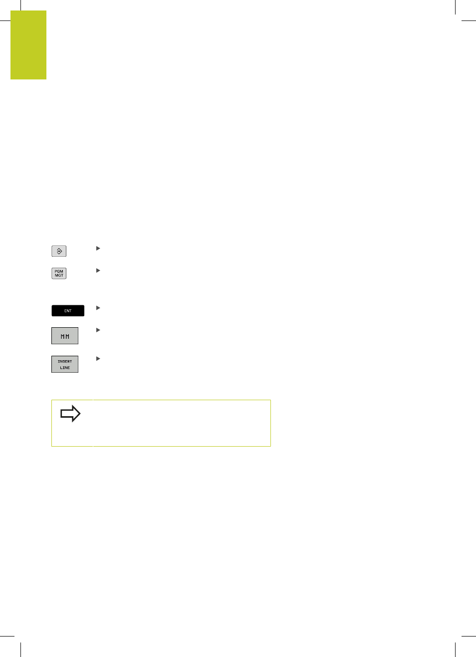
Creating a point table
Select the
Programming mode of operation
Call the file manager: Press the
PGM MGT key.
FILE NAME?
Enter the name and file type of the point table and
confirm your entry with the
ENT key.
Select the unit of measure: Press the
MM or INCH
soft key. The TNC changes to the program blocks
window and displays an empty point table.
With the
INSERT LINE soft key, insert new
lines and enter the coordinates of the desired
machining position.
Repeat the process until all desired coordinates have been entered.
The name of the point table must begin with a letter.
Use the soft keys
X OFF/ON, Y OFF/ON, Z OFF/ON
(second soft-key row) to specify which coordinates
you want to enter in the point table.