1 measur ing w o rk piece misalignment – HEIDENHAIN iTNC 530 (340 49x-04) Touch Probe Cycles User Manual
Page 58
58
3 Touch Probe Cycles for Automatic Workpiece Inspection
3.1 Measur
ing W
o
rk
piece Misalignment
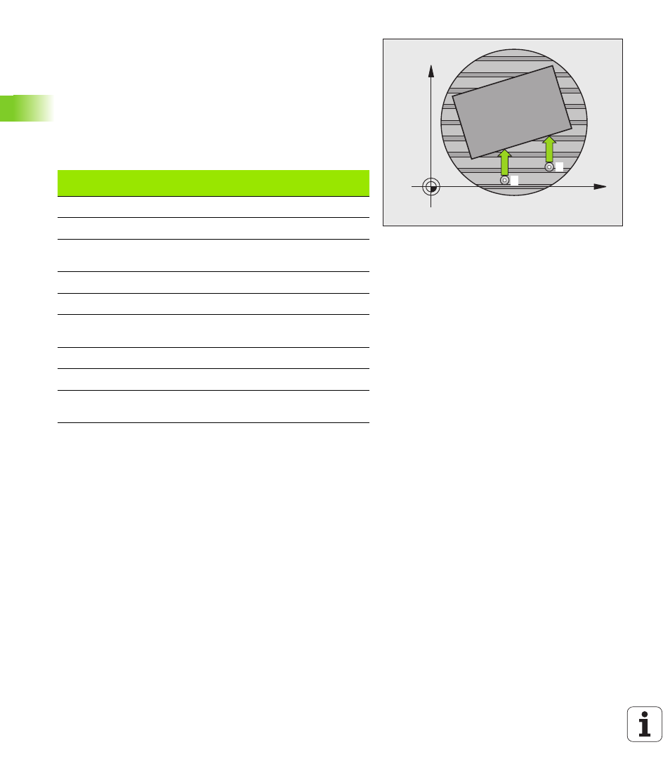
BASIC ROTATION compensation via rotary axis
(touch probe cycles 403, DIN/ISO: G403)
Touch probe cycle 403 determines a workpiece misalignment by
measuring two points, which must lie on a straight surface. The TNC
compensates the determined misalignment by rotating the A, B or C
axis. The workpiece can be clamped in any position on the rotary table.
The combinations of measuring axis (Cycle Parameter Q272) and
compensation axis (Cycle Parameter Q312) listed below are
permitted. Function for tilting the working plane:
1
The TNC positions the touch probe to the starting points at rapid
traverse (value from MP6150 or MP6361) following the positioning
logic (see “Running touch probe cycles” on page 26) to the
programmed starting point
1
. The TNC offsets the touch probe by
the safety clearance in the direction opposite the defined traverse
direction.
2
Then the touch probe moves to the entered measuring height and
probes the first touch point at the probing feed rate (MP6120 or
MP6360).
3
Then the touch probe moves to the next starting position
2
and
probes the second position.
X
Y
1
2
Active TX axis
Measuring axis
Compensation
axis
Z
X (Q272=1)
C (Q312=6)
Z
Y (Q272=2)
C (Q312=6)
Z
Z (Q272=3)
B (Q312=5) or A
(Q312=4)
Y
Z (Q272=1)
B (Q312=5)
Y
X (Q272=2)
C (Q312=5)
Y
Y (Q272=3)
C (Q312=6) or A
(Q312=4)
X
Y (Q272=1)
A (Q312=4)
X
Z (Q272=2)
A (Q312=4)
X
X (Q272=3)
B (Q312=5) or C
(Q312=6)