Graphics during fk programming – HEIDENHAIN iTNC 530 (340 49x-05) User Manual
Page 223
HEIDENHAIN iTNC 530
223
6.6 P
a
th Cont
ours—FK F
ree Cont
our Pr
ogr
a
mming
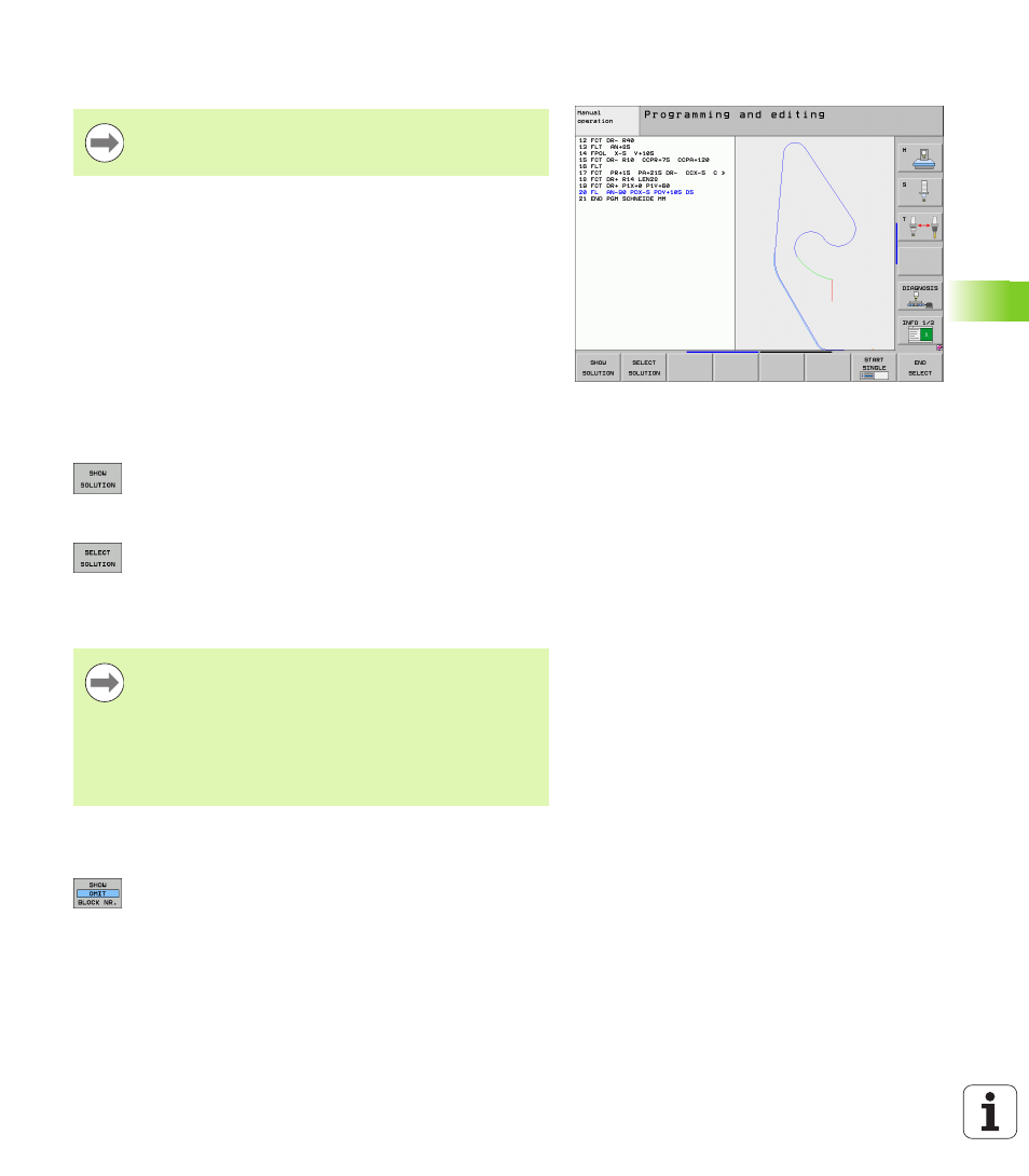
Graphics during FK programming
Incomplete coordinate data often are not sufficient to fully define a
workpiece contour. In this case, the TNC indicates the possible
solutions in the FK graphic. You can then select the contour that
matches the drawing. The FK graphic displays the elements of the
workpiece contour in different colors:
If the entered data permit a limited number of possible solutions and
the contour element is displayed in green, select the correct contour
element as follows:
U
Press the SHOW SOLUTION soft key repeatedly until
the correct contour element is displayed. Use the
zoom function (2nd soft-key row) if you cannot
distinguish possible solutions in the standard setting
U
If the displayed contour element matches the
drawing, select the contour element with SELECT
SOLUTION
If you do not yet wish to select a green contour element, press the
EDIT soft key to continue the FK dialog.
Show block number in graphic window
To show a block number in the graphic window:
U
Set the SHOW OMIT BLOCK NR. soft key to SHOW
(soft-key row 3)
If you wish to use graphic support during FK
programming, select the PROGRAM + GRAPHICS screen
layout (see “Programming and Editing” on page 79).
Blue
The contour element is fully defined
Green
The entered data describe a limited number of possible
solutions: select the correct one
Red
The entered data are not sufficient to determine the
contour element: enter further data
Select the green contour elements as soon as possible
with the SELECT SOLUTION soft key. This way you can
reduce the ambiguity of subsequent elements.
The machine tool builder may use other colors for the FK
graphics.
NC blocks from a program that you called with PGM CALL
are displayed in another color.