Application, Working without additional traverse limits, Find and enter the maximum traverse – HEIDENHAIN iTNC 530 (340 49x-06) User Manual
Page 647
HEIDENHAIN iTNC 530
647
1
7.14 Ent
er
ing the Axis T
ra
v
erse Limits, D
a
tu
m Displa
y
17.14 Entering the Axis Traverse
Limits, Datum Display
Application
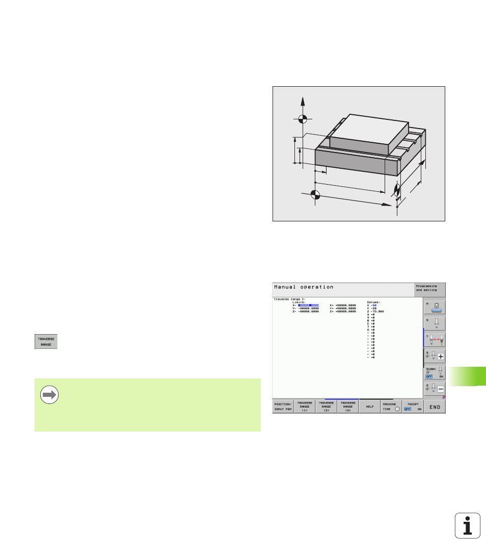
The AXIS LIMIT MOD function allows you to set limits to axis traverse
within the machine’s actual working envelope.
Possible application: Protecting an indexing fixture against tool
collision.
The maximum range of traverse of the machine tool is defined by
software limit switches. This range can be additionally limited through
the TRAVERSE RANGE MOD function. With this function, you can
enter the maximum and minimum traverse positions for each axis,
referenced to the machine datum. If several traverse ranges are
possible on your machine, you can set the limits for each range
separately using the soft keys TRAVERSE RANGE (1) to TRAVERSE
RANGE (3).
Working without additional traverse limits
To allow a machine axis to use its full range of traverse, enter the
maximum traverse of the TNC (+/- 99 999 mm) as the TRAVERSE
RANGE.
Find and enter the maximum traverse
U
Set the Position display MOD function to REF.
U
Move the spindle to the positive and negative end positions of the
X, Y and Z axes
U
Write down the values, including the algebraic sign
U
To select the MOD functions, press the MOD key.
U
Enter the limits for axis traverse: Press the TRAVERSE
RANGE soft key and enter the values that you wrote
down as limits in the corresponding axes
U
To exit the MOD function, press the END soft key.
Z
Y
X
Z
min
Z
max
X
min
Y
max
Y
min
X
max
Active tool radius compensations are not taken into
account in the axis traverse limit values.
The traverse range limits and software limit switches
become active as soon as the reference points are
traversed.