HEIDENHAIN iTNC 530 (34049x-08) Cycle programming User Manual
Page 436
436
Touch probe cycles: automatic workpiece inspection
16.8 MEA
S
URE RECT
ANGLE OUTSIDE (Cy
cle 424, DIN/ISO:
G424)
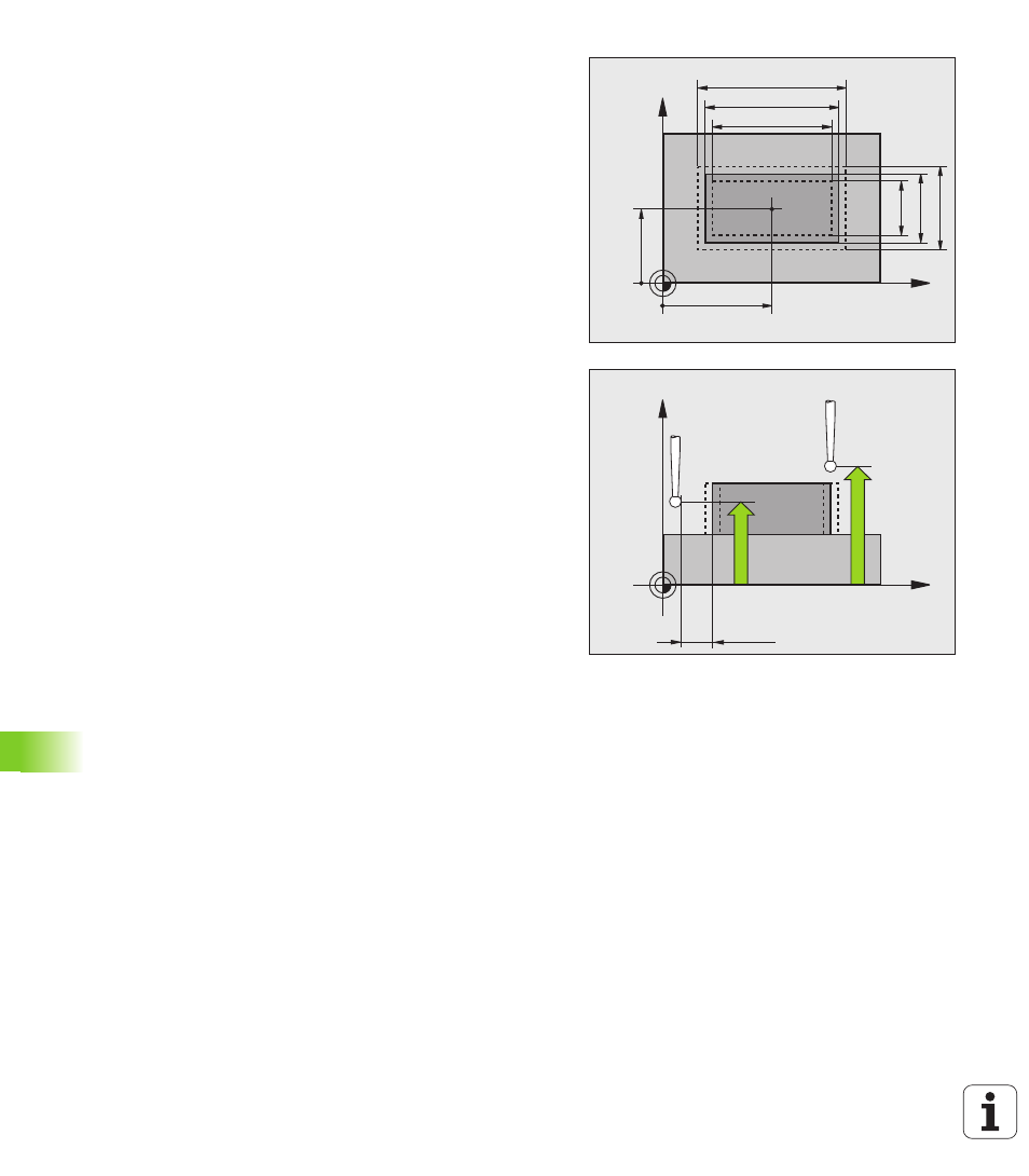
Set-up clearance
Q320 (incremental): Additional
distance between measuring point and ball tip. Q320
is added to MP6140. Input range 0 to 99999.9999,
alternatively PREDEF
Clearance height
Q260 (absolute): Coordinate in the
touch probe axis at which no collision between touch
probe and workpiece (fixtures) can occur. Input range
-99999.9999 to 99999.9999, alternatively PREDEF
Traversing to clearance height
Q301: Definition of
how the touch probe is to move between the
measuring points:
0
: Move at measuring height between measuring
points
1
: Move at clearance height between measuring
points
Alternatively PREDEF
Max. size limit 1st side length
Q284: Maximum
permissible length of the stud. Input range 0 to
99999.9999
Min. size limit 1st side length
Q285: Minimum
permissible length of the stud. Input range 0 to
99999.9999
Max. size limit 2nd side length
Q286: Maximum
permissible width of the stud. Input range 0 to
99999.9999
Min. size limit 2nd side length
Q287: Minimum
permissible width of the stud. Input range 0 to
99999.9999
Tolerance for center 1st axis
Q279: Permissible
position deviation in the reference axis of the working
plane. Input range 0 to 99999.9999
Tolerance for center 2nd axis
Q280: Permissible
position deviation in the minor axis of the working
plane. Input range 0 to 99999.9999
X
Y
Q287
Q285
Q274
±Q280
Q273
±Q279
Q283
Q286
Q282
Q284
X
Z
Q260
Q261
MP6140
+
Q320