2 tool data, Requirements for tool compensation, Tool numbers and tool names – HEIDENHAIN TNC 620 (73498x-01) User Manual
Page 146: Tool length l, Tool radius r, 2 t ool data 5.2 tool data
146
Programming: Tools
5.2 T
ool data
5.2 Tool data
Requirements for tool compensation
You usually program the coordinates of path contours as they are
dimensioned in the workpiece drawing. To allow the TNC to calculate
the tool center path—i.e. the tool compensation—you must also enter
the length and radius of each tool you are using.
Tool data can be entered either directly in the part program with
TOOL DEF
or separately in a tool table. In a tool table, you can also enter
additional data for the specific tool. The TNC will consider all the data
entered for the tool when executing the part program.
Tool numbers and tool names
Each tool is identified by a number between 0 and 32767. If you are
working with tool tables, you can also enter a tool name for each tool.
Tool names can have up to 16 characters.
The tool number 0 is automatically defined as the zero tool with the
length L=0 and the radius R=0. In tool tables, tool T0 should also be
defined with L=0 and R=0.
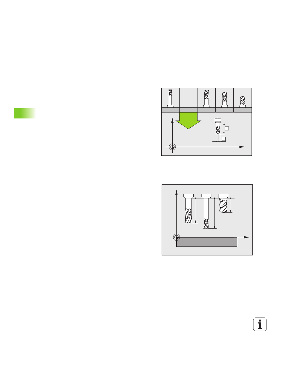
Tool length L
You should always enter the tool length L as an absolute value based
on the tool reference point. The entire tool length is essential for the
TNC in order to perform numerous functions involving multi-axis
machining.
Tool radius R
You can enter the tool radius R directly.
Z
X
1
18
13
12
8
R
L
8
Z
X
L3
L2
L1