Zero point for polar coordinates: pole cc, Straight line lp, Path contours – polar coordinates 6.5 – HEIDENHAIN TNC 640 (34059x-04) User Manual
Page 225
Path contours – Polar coordinates
6.5
6
TNC 640 | User's Manual
HEIDENHAIN Conversational Programming | 3/2014
225
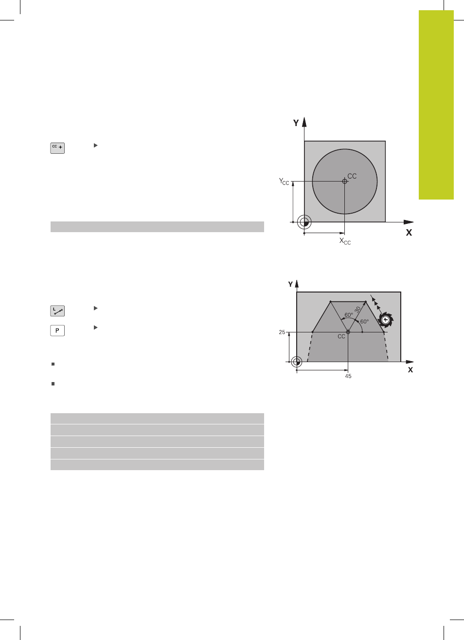
Zero point for polar coordinates: pole CC
You can define the pole CC anywhere in the part program before
blocks containing polar coordinates. Set the pole in the same way
as you would program the circle center.
Coordinates: Enter Cartesian coordinates for the
pole or, if you want to use the last programmed
position, do not enter any coordinates. Before
programming polar coordinates, define the
pole. You can only define the pole in Cartesian
coordinates. The pole remains in effect until you
define a new pole.
Example NC blocks
12 CC X+45 Y+25
Straight line LP
The tool moves in a straight line from its current position to the
straight-line end point. The starting point is the end point of the
preceding block.
Polar coordinate radius PR: Enter the distance
from the pole CC to the straight-line end point.
Polar coordinate angle PA: Angular position of the
straight-line end point between –360° and +360°
The sign of
PA depends on the angle reference axis:
If the angle from the angle reference axis to
PR is
counterclockwise:
PA>0
If the angle from the angle reference axis to
PR is clockwise:
PA<0
Example NC blocks
12 CC X+45 Y+25
13 LP PR+30 PA+0 RR F300 M3
14 LP PA+60
15 LP IPA+60
16 LP PA+180