Control circuit output terminals, Table i.9 – Yaskawa AC Drive Z1000 HVAC User Manual
Page 29
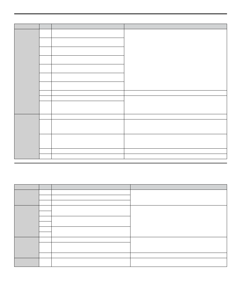
Table i.9 Control Circuit Input Terminals
Type
No.
Terminal Name (Function)
Function (Signal Level) Default Setting
Multi-Function
Digital Inputs
S1
Multi-function input 1
(Closed: Forward run, Open: Stop)
• Photocoupler
• 24 Vdc, 8 mA
• Set the wire jumper to select between sinking, sourcing mode, and the
Refer to Sinking/Sourcing Mode Switch for Digital
S2
Multi-function input 2
(Closed: Reverse run, Open: Stop)
S3
Multi-function input 3
(External fault, N.O.)
S4
Multi-function input 4
(Fault reset)
S5
Multi-function input 5
(Multi-step speed reference 1)
S6
Multi-function input 6
(Multi-step speed reference 2)
S7
Multi-function input 7
(Jog reference)
SC
Multi-function input common
Multi-function input common
SP
Digital input power supply +24 Vdc
24 Vdc power supply for digital inputs, 150 mA max
NOTICE: Do not jumper or short terminals SP and SN. Failure to
comply will damage the drive.
SN
Digital input power supply 0 V
Frequency
Reference
Inputs
+V
Power supply for analog inputs
10.5 Vdc (max allowable current 20 mA)
A1
Multi-function analog input 1
(Frequency reference bias)
• 0 to 10 Vdc/100% (input impedance: 20 kΩ)
• 4 to 20 mA/100%, 0 to 20 mA/100% (input impedance: 250 Ω)
• Voltage or current input must be selected by Jumper S1 and H3-01.
A2
Multi-function analog input 2
(Frequency reference bias)
• 0 to 10 Vdc/100% (input impedance: 20 kΩ)
• 4 to 20 mA/100%, 0 to 20 mA/100% (input impedance: 250 Ω)
• Voltage or current input must be selected by Jumper S1 and H3-09.
AC
Frequency reference common
0 V
FE
Ground for shielded lines and option cards
–
u
Control Circuit Output Terminals
lists the output terminals on the drive. Text in parenthesis indicates the default setting for each multi-function output.
Table i.10 Control Circuit Output Terminals
Type
No.
Terminal Name (Function)
Function (Signal Level) Default Setting
Fault Relay
Output
MA
N.O.
30 Vdc, 10 mA to 2 A; 250 Vac, 10 mA to 2 A
Minimum load: 5 Vdc, 10 mA
MB
N.C. output
MC
Fault output common
Multi-Function
Digital Output
<1>
M1
Multi-function digital output (During run)
30 Vdc, 10 mA to 2 A; 250 Vac, 10 mA to 2 A
Minimum load: 5 Vdc, 10 mA
M2
M3
Multi-function digital output (Zero speed)
M4
M5
Multi-function digital output (Speed Agree 1)
M6
Monitor Output
FM
Analog monitor output 1 (Output frequency)
0 to 10 V / 0 to 100%
4 to 20 mA / 0 to 100%
Voltage or current output must be selected by Jumper S5 and H4-07
for FM and H4-08 for AM.
AM
Analog monitor output 2 (Output current)
AC
Monitor common
0 V
External Power
Supply
+P
External Power Supply
24 V (Max. 150 mA)
<1> Refrain from assigning functions to digital relay outputs that involve frequent switching, as doing so may shorten relay performance life. Switching
life is estimated at 100,000 times (assumes 2 A, resistive load).
Connect a suppression diode as shown in
when driving a reactive load such as a relay coil. Ensure the diode rating
is greater than the circuit voltage.
i.3 Electrical Installation Safety
YASKAWA ELECTRIC TOEP YAIZ1U 01A YASKAWA AC Drive – Z1000 Safety Precautions
29