Diaphragm replacement, Valve seats – Jordan Valve Mark 50 Series – Self-Operated Back Pressure Regulator User Manual
Page 2
Once the orifices in the plate and disc are prop-
5.
erly aligned, place a straight edge across the body
bolt holes on the horizontal center line of the valve
(perpendicular to the valve movement.) Gently ro-
tate the disc and plate assembly until the edges of
the orifice slots are parallel to the straight edge and
replace the cap, being careful not to rotate the disc
and plate assembly.
Replace the cap and cap bolts, and tighten uniform-
6.
ly, being careful not to torque excessively. See back
page for recommended torque values.
Diaphragm Replacement
A. DISASSEMBLY
In removing the diaphragm, you must first remove
1.
the valve disc and valve plate. This is outlined under
VALVE SEATS.
Remove the compression of the adjusting spring by
2.
rotating the adjusting screw counterclockwise.
Remove the spring housing bolts and spring hous-
3.
ing. Remove adjusting spring and spring seat.
Hold the disc pin with an open end wrench and
4.
remove the diaphragm assembly by rotating coun-
terclockwise. The diaphragm assembly consists of
the upper diaphragm plate, diaphragm, and lower
diaphragm plate.
If the diaphragm must be replaced, secure the upper
5.
diaphragm plate in the vise. A face spanner wrench
should be used to remove the lower diaphragm
plate from the assembly. If a face spanner wrench
is not available, use a punch and hammer, but make
certain to remove all burrs prior to reassembling.
B.
ASSEMBLY AND STROKE ADJUSTMENT
The valve stroke adjustment is determined by how
1.
far the diaphragm assembly is screwed onto the
stem. Hold the disc pin with an open end wrench
and screw the diaphragm assembly onto the valve
stem all the way, and back off two turns initially.
To check the stroke adjustment, put the pressure
2.
ring, valve disc, and valve plate in position in the
valve body, using the same precautions outlined un-
der VALVE SEATS.
Secure the spring housing to the valve body with
3.
two spring housing bolts and tighten.
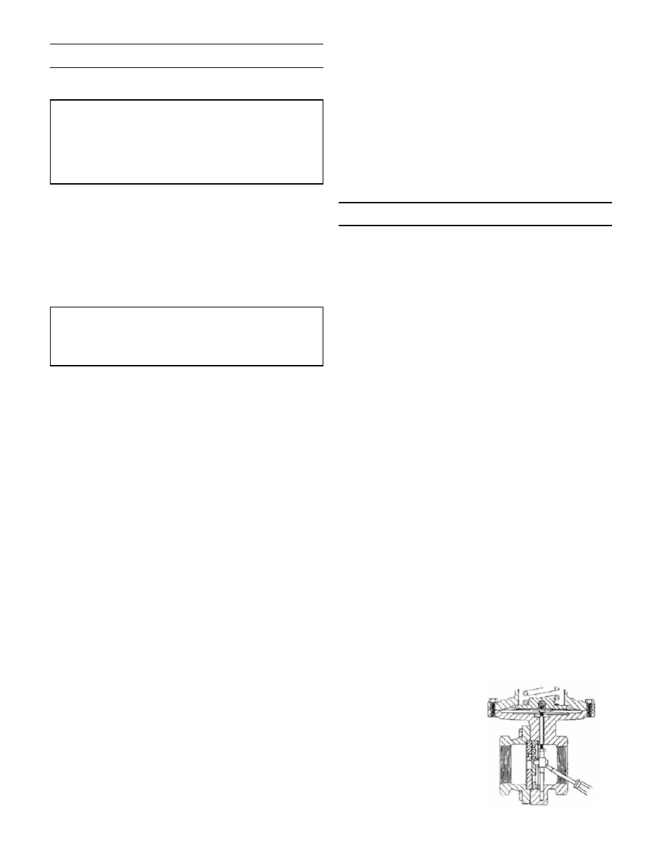
Using a small screw-
4.
driver through the
upstream opening of
the valve body, stroke
the valve against the
upper travel stop of
the spring housing.
The orifices should
be aligned in the full
open position.
Valve Seats
A. DISASSEMBLY
The seats of Jordan regulators are precision-
lapped. Maintaining such tolerances is of para-
mount importance for your assurance of excel-
lent control and tight shutoff. Do not use metallic
objects in removing the seats. Care in handling
is imperative.
Close shutoff valve on each side of the regulator.
1.
Remove the regulator from line.
2.
Secure the inlet body hex in the vise. Remove the
3.
cap bolts and lift cap straight up.
Remove the disc and plate assembly by lifting the
4.
assembly straight up from the valve body. Place the
assembly on the bench with the disc up. Remove
the pressure ring.
SPECIAL NOTE: It is imperative that the disc pin
is not rotated in disassembly, cleaning, or reas-
sembly, since this affects the stroke adjustment
of the valve.
Clean the plate seat with fine emery cloth. Clean the
5.
body and cap cores with good quality solvent.
To clean the disc and plate, remove the guide screws.
6.
Place 4/0 polishing cloth or jeweler’s cloth on a
smooth, flat surface, and polish the lapped surfaces
of the disc and plate. If these parts are scarred, do
not attempt to re-lap them, but return them to the
factory for repair or replacement. The pressure ring
may be polished in the same manner.
B.
REASSEMBLY
Place disc on the plate and replace the guide
1.
screws. Tighten the guide screws but do not allow
the screws to bind the disc against the plate.
Replace the pressure ring and the disc/plate assem-
2.
bly. Make sure that the disc pin engages the disc
and that the plate seats solidly against the plate seat
in the body.
Check the orifice alignment of the disc and plate
3.
by releasing the compression of the range spring
and then stroking the valve fully upwards. (To stroke
valve upwards, pry the disc pin upwards with a
screwdriver through the inlet of the valve -- see fig-
ure on next page.) In this position, the orifices of
the disc and plate must be fully open and in perfect
alignment. If the orifices are not aligned, the disc
pin has probably been rotated. Remove the disc and
plate assembly and rotate the disc pin to raise it or
lower it for proper alignment.
If further adjustment of the disc pin does not pro-
4.
vide perfect alignment, proceed to VALVE STROKE
ADJUSTMENT.
-2-