Disc pin and stem, Troubleshooting, Torque values – Jordan Valve Mark 50 Series – Self-Operated Back Pressure Regulator User Manual
Page 3: Ordering spare parts
-3-
If the orifices are not aligned in the open position,
5.
remove the spring housing and rotate the diaphragm
assembly counterclockwise to lower the disc, and
clockwise to raise the disc.
A further check on the stroke adjustment can be
6.
made by checking the orifices in the closed position.
This is a “normally closed” valve, and there should
be a 1/32” overlap when the diaphragm assembly is
down against the valve body.
Remove the valve plate and the valve disc to elimi-
7.
nate the possibility of damage during the topworks
reassembly.
Reassemble the adjusting spring and spring seat.
8.
Before replacing the spring housing, make certain
9.
that the diaphragm is centered in the body recess.
This recess aligns the spring housing and dia-
phragm.
In replacing the spring housing, make certain that it
10.
seats properly in the valve body recess.
Replace the spring housing bolts and tighten only fin-
11.
ger tight. Thread the adjusting screw into the spring
housing until the seats are in their fully closed posi-
tion. Tighten the spring housing bolts to the torque
values shown on the last page of this document.
Replace the pressure ring, disc, plate, and cap.
12.
See last page of this document for recommended
torque.
Disc Pin and Stem
Remove the valve disc and valve plate as explained
1.
under VALVE SEATS.
Remove the diaphragm and topworks as described
2.
under DIAPHRAGM REPLACEMENT.
Hold the disc pin with an open end wrench and loos-
3.
en the locknut. Now the stem may be unscrewed
from the disc pin and removed.
To reassemble, first insert the disc pin into the valve
4.
body; followed by the stem and locknut. Screw the
stem into the disc pin about 1/4” or midway on the
stem threads and lock the locknut against the disc
pin.
To reassemble the diaphragm and topworks and
5.
valve seats, refer to the reassembly instructions
under VALVE SEATS and DIAPHRAGM REPLACE-
MENT.
Troubleshooting
If You Experience Erratic Control:
Oversizing causes cycling and hunting, and reduces
the rangeability of the valve. Make certain that your
sizing is correct.
Excessive foreign matter may be on seats; clean
seats.
Valve stroke may be out of adjustment; readjust and
tighten locknuts securely.
Valve disc may not be moving freely; inspect and
clean.
Moving parts may be binding; inspect and realign or
replace if necessary.
If Valve Will Not Operate:
Diaphragm may be ruptured and require replace-
ment.
Adjusting spring may be broken and require re-
placement.
Spring may be set improperly and require resetting.
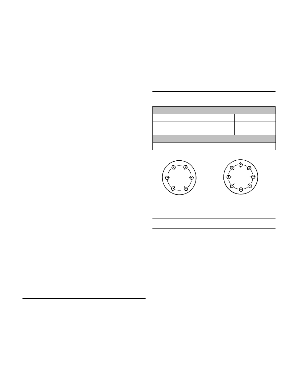
Torque Values
Torque for Valve Cap to Valve Body Bolts
Cast Iron or Bronze
140 in/lbs
Ductile Iron, Carbon Steel or
Stainless Steel
200 in/lbs
Torque for Spring Housing Bolts
170 in/lbs
Ordering Spare Parts
Use only genuine Jordan Valve parts to keep your valve
in good working order. So we can supply the parts, which
were designed for your valve, we must know exactly which
product you are using. The only guarantee to getting the
correct replacement parts is to provide your Jordan Rep-
resentative with the valve serial number. This number is
located on the valve identification tag. If the serial number
is not available, the parts needed for your valve might be
determined using the following information: Model num-
ber, Valve Body size, Plug Material and Seat Size, Spring
Range or Set Point, Trim Material, Part Name - Number
and Quantity (see parts list chart).
Note: Without a valve serial number, any parts ordered
incorrectly are subject to a minimum 25% restock charge
when returned.
5
3
1
6
4
2
5
3
1
6 4
2
7
8
6 bolts
(or multiples)
8 bolts
(or multiples)