Reversing tempilot action, Calibration, Both air and water controller – Jordan Valve Mark 25 Series – Tempilot Temperature User Manual
Page 2
2.
Install Lever (6). Tighten the Lever Pivot Screws (21)
as required. The Lever must be in the exact center
of the body and must move freely but without side
play. (For Water only — seal Lever Pivot Screws with
Loctite Grade E.)
3.
Install Screws (22).
4.
Install parts (8) and (9). (Note relationship for Direct
and Reverse Acting.)
5.
Back up Adjustment Screw (5) until Collar (19) touch-
es the Pivots on Lever (6).
6.
Install Cover Assembly (2).
7.
Install Adjustment Knob (3). The notch on Knob (3)
should be opposite the dial marking correspond-
ing to the room temperature. Tighten the Knob Set
Screw very firmly.
8.
Turn the Adjustment Knob to the desired control
temperature for an approximate calibration.
9.
Recalibrate as required after the controller is installed
and connected to the supply and control lines.
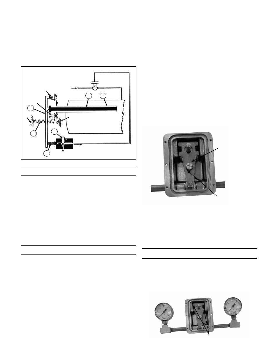
Please note Figure 2. This figure shows how the lever
spring and the lever spring retainer should be assembled
in front of the lever for direct acting regulators. Also note
that the lever pivots and the lever pivot set screws are as-
sembled in the top two pivots for a direct acting Tempilot
Reversing Tempilot Action
Please note Figure 3. Since this is a reverse acting Tem-
pilot, the lever spring retainer is in front of the lever, and
the lever spring is behind the lever. Also, the lever pivots
and the lever pivot set screws are in the lower two pivot
points.
O.D. copper tubing.
4.
The difference in height between the Tempilot and
the control valve should be kept to a minimum.
When the regulator is below the control valve, the
elevation cannot exceed 10’ with a 15 psi supply
pressure. If the Tempilot is above the control valve,
adjust springs on the valve to compensate for the
static head pressure.
Calibration
1.
To calibrate the Tempilot, turn the adjusting knob
until a 7-1/2” psi control pressure shows on the
gauge.
2.
Read the temperature at the bulb with an accurate
thermometer.
3.
Loosen the set screw in the adjusting knob and turn
the adjusting knob to indicate the temperature at
the bulb.
4.
Tighten the set screw.
5.
Now set the Tempilot for the desired temperature for
your process.
Both Air and Water Controller
A. Disassembly (Refer to Figure 4 on page 3)
1.
Remove Knob (3) after loosening its Set Screw.
2.
Remove Cover Assembly (2).
3.
Remove Lever Spring Retainer (8) and Lever Spring
(9).
4.
Back up one Lever Pivot (21) and remove Lever (6).
5.
Unscrew Sensitive Tube Assembly (20) from Body
(1).
B.
Assembly
1.
Install new Sensitive Tube Assembly (20) to body
(1).
-2-
Positions “B” and “D” (dotted)
show pivot point (B) and spring
location (D) for reverse acting
regulator.
Valve
(Normally
Open)
2
3
5
4
6
1
B
A
D
C
S
R
Figure 1
Lever Spring
Retainer
Direct Acting spring
in front of lever. For
Reverse Acting, place
spring behind lever.
Figure 2
Set Screws (Reverse Acting)
Figure 3