Jordan Valve Mark 4150 Series Pressure Controllers User Manual
Page 4
-4-
Pressure Setting Adjustment
The Mark 4150 and 4160 come with calibrated set point
adjustment. The dial is calibrated for pressure ratings
of the measurement element. If start up instructions are
followed, the pressure setting dial is correct for any set-
tings on proportional-reset controllers.
Mark 4150 Pressure Controller
The theory of operation can be broken down into steps.
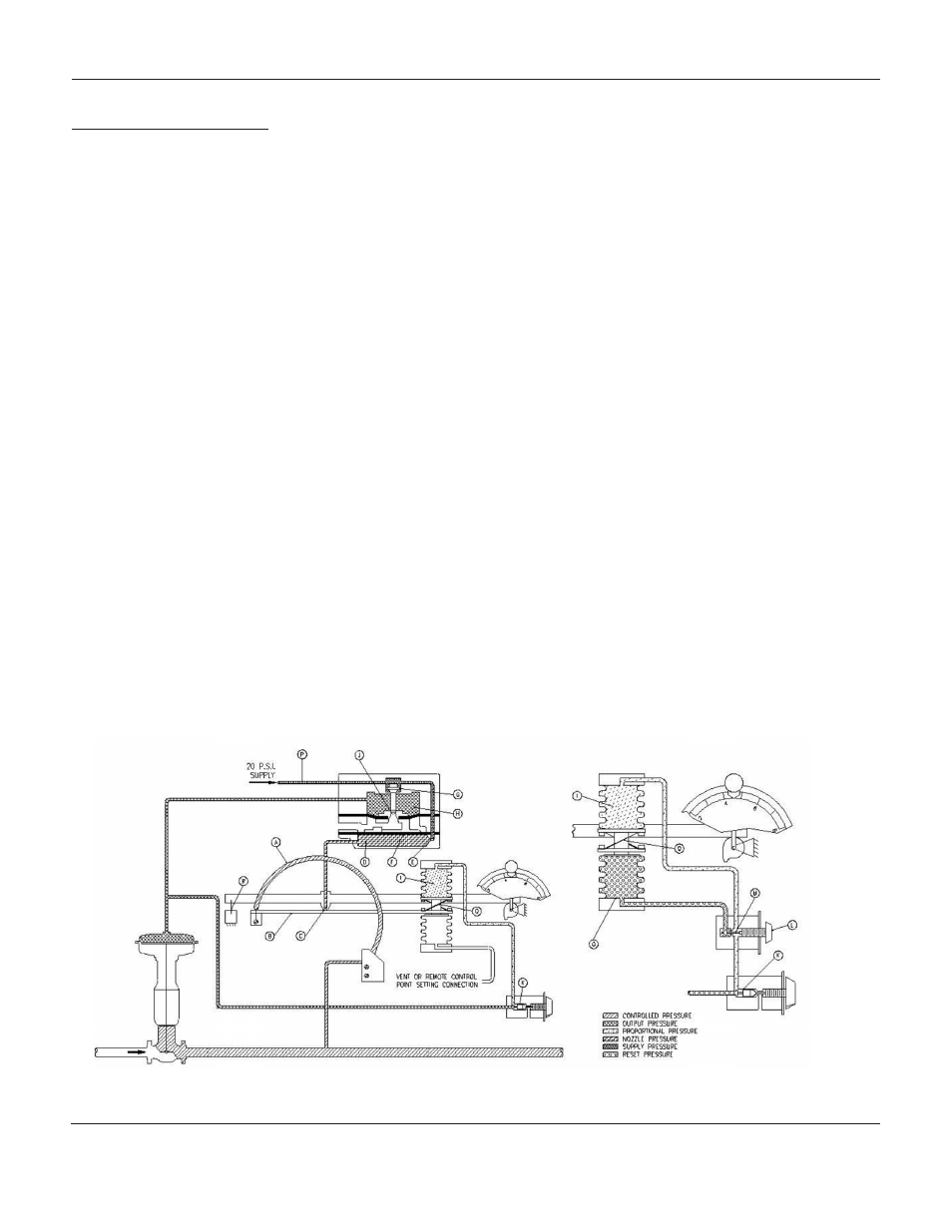
Refer to the schematic diagram figure 3.
I.
The pressure first enters the Bourdon tube. As
the pressure increases the Bourdon tube
straightens causing the beam (B) attached to
the end of the Bourdon tube to move closer to
nozzle (C).
2.
Closing the nozzle (C) will cause a build up of
pressure in chamber (D) from the constant air or
gas supply through the orifice (E).
3.
The resulting pressure built up in chamber (D)
cause the diaphragm (F) to push up and
open valve (G).
4.
An open Valve (G) will cause the constant air or
gas supply to flow into chamber (H).
5.
The build up of pressure in chamber (H) causes
diaphragm (F) to be pushed back to its original
position and therefore closes valve (G).
6.
The increase in pressure in chamber (H) sends
the supply pressure to flow to the diaphragm
of the control valve causing the control valve to
start to close.
7.
At the same time, the pressure flows through the
three-way valve (K) causing an increase in pres
sure in bellows (I).
8.
The increase in the pressure bellows (I) cause
the beam (B) to move away from nozzle (C). As
a result there will no longer be a build up of
pressure in (D). The control valve is now at the
desired pressure setting.
If there is a decrease in control pressure the above men-
tioned steps will proceed in reverse. The control pres-
sure will bleed out through the exhaust vent (J).
Please note that the changes in pressure are continuous
in nature. The process has been explained in steps for
ease of explanation.
As seen in the figure 3, schematic illustration of Mark
4150, the output pressure from relay chamber (H) goes
to both the proportional band adjustment relay three-way
valve (K) and the control valve diaphragm. The amount
of feedback to the proportional bellows (I) can be ad-
justed by adjusting the orifice. If valve (K) is fully open,
then the total of the diaphragm pressure is sent to the
bellows chamber (I).
This causes the beam (B) to move away from nozzle (C)
allowing the pressure to be released from chamber (D).
The result of this is 100% proportional band based on
the rating of the Bourdon tube. Closing the three-way
valve (K) will result in a lowering of proportional band re-
sponse. The proportional band would be approximately
3% when fully closed.
Figure 3:
Schematic Illustration of
Mark 4150 Proportional Controller
Schematic Illustration of Mark 4150
Proportional-Reset Controller
M
ark
4150
and
4160 S
erieS
P
reSSure
C
ontrollerS