Front panel features, Front panel features 3, Chapter 1 – Lanner LEC-3000A User Manual
Page 5: Introduction
3
Introduction
Chapter 1
Embedded and Industrial Computing
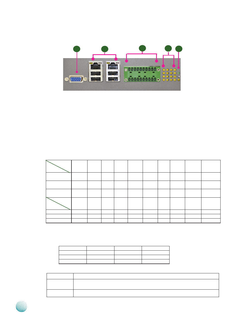
F1 VGA Port
Using suitable DB-15 cable, you can connect an appropriate device such as a monitor
F2 Four USB 2 0 type A ports
It connects to any USB devices, for example, a flash drive
Two 10/100/1000Mbps LAN ports (LAN1:left, LAN2:right)
Using suitable RJ-45 cable, you can connect LEC-3000A System to a computer, or to any other piece of equipment
that has an Ethernet connection such as a hub or a switch
F3 20-pin Phoenix Contact Terminal Block
This connector can be connected for 4 Com ports (COM4: Pin 1~5, Com3: Pin 6~10, Com2: Pin11~15, Com1: Pin
16~20) with serial port type of RS-232, RS-422 or RS-485; it supports dip switch selection of RS-232, RS-422 and
485 The following table lists the pin assignments
Pin NO.
Port Type
Pin 1
Pin 2
Pin 3
Pin 4
Pin 5
Pin 6
PIN7
PIN 8
PIN 9
Pin10
RS-232
Ground
(GND)
CTS4# SOUT4 SIN4
RTS4#
GND CTS3# SOUT3
SIN3
RTS3#
RS-422
Ground
(GND)
RX-
RX+
TX+
TX-
GND
RX-
RX+
TX+
TX-
RS-485
Ground
(GND)
NC
NC DATA+ DATA-
GND
NC
NC
DATA+
DATA-
Pin NO.
Port Type
Pin 11
Pin 12 Pin 13 Pin 14
Pin 15
Pin 16 Pin 17 Pin 18
Pin 19
Pin 20
RS-232
GND
CTS2# SOUT2 SIN2
RTS2#
GND CTS1# SOUT1
SIN1
RTS1#
RS-422
GND
RX-
RX+
TX+
TX-
GND
RX-
RX+
TX+
TX-
RS-485
GND
NC
NC DATA+ DATA-
GND
NC
NC
DATA+
DATA-
F4 Serial Port Status LED
The left two columns are LED indicators of Digital Output/Input
The right two columns are LED indicators of Tx (Data transmitting) and RX (Data receiving) for Serial Port Status
Front Panel Features
F4
F1
F5
F2
1 2 3 4 5 6 7 8 9 10
11 12 13 14 1516 17 18 19 20
F3
DO-Pin 1
DI-Pin 1
RX-Com 1
TX-Com 1
DO-Pin 2
DI-Pin 2
RX-Com 2
TX-Com 2
DO-Pin 3
DI-Pin 3
RX-Com 3
TX-Com 3
DO-Pin 4
DI-Pin 4
RX-Com 4
TX-Com 4
F5 Power/Status/HDD LED
Power
Green indicates Power-on, where as Off indicates Power-off status.
Run
A programmable dual green/orange LEDs which can be used for indicating system
status.
Hard Disk
Yellow indicates that HDD is present, whereas Off indicates HDD is not present.