Chapter 3, Chapter 3: board layout, Board layout – Lanner LEC-3013 User Manual

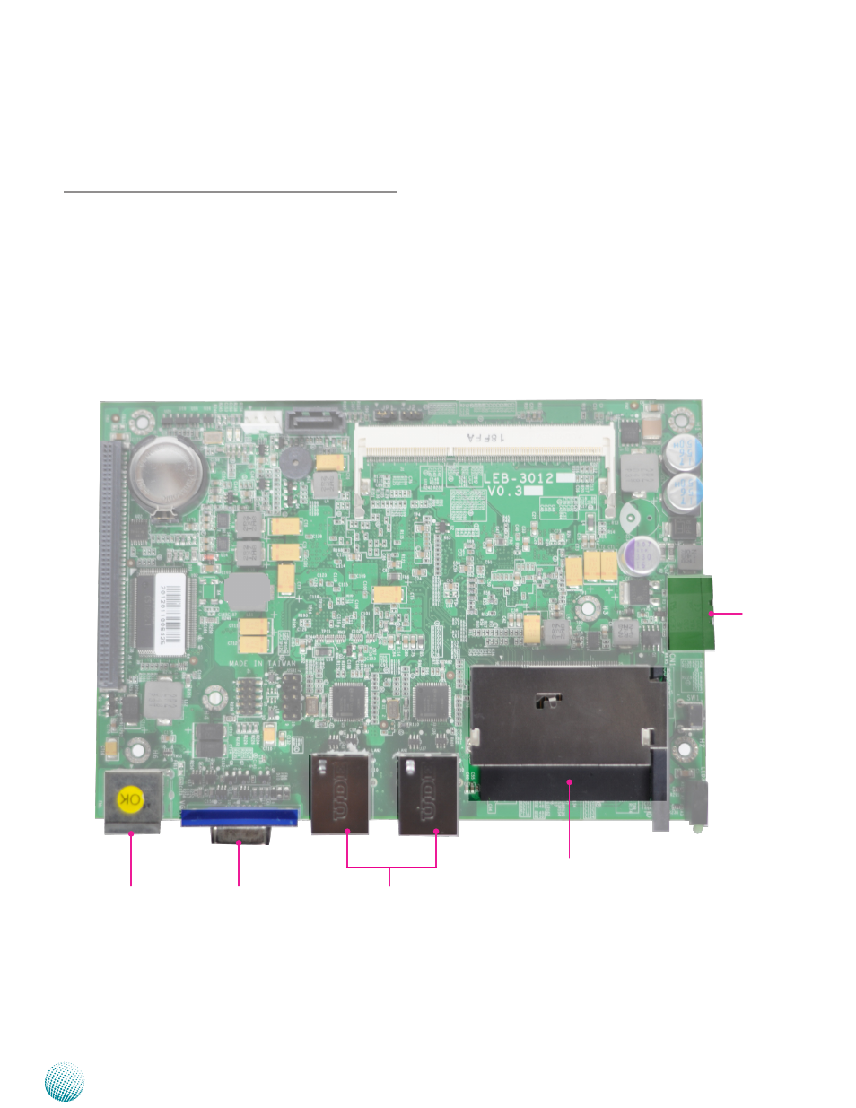
Page 11: External connectors

Advertising
background image

11

Board Layout

Chapter 3

Embedded and Industrial Computing

Chapter 3:

Board Layout

External Connectors

The following picture highlights the location of system

input/output connectors. Refer to the table 3.1 Connector

List for more details.

CN3

VGA1

CN2

LAN2/LAN1

CN1

Advertising
This manual is related to the following products: