Chapter 2, System components – Lanner LEC-3013 User Manual
Page 9
9
System Components
Chapter 2
Embedded and Industrial Computing
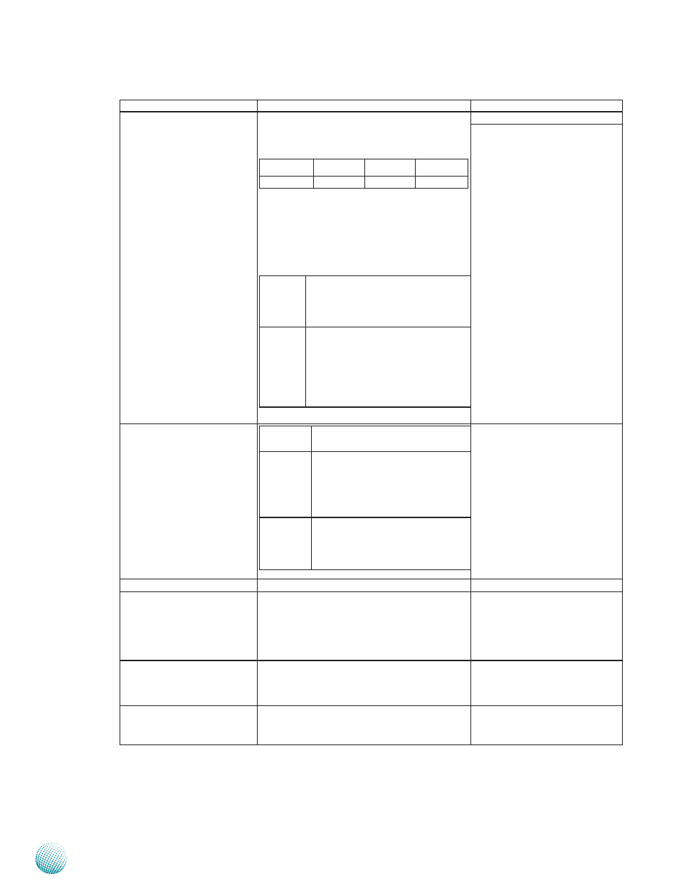
Component
Description
Pin Definition Reference
F2 Serial Port and LAN Port
LED
These four roles are LED indicators of Tx (Data
transmitting in yellow) and RX (Data receiving
in green) for serial port status.
TX-COM 4 RX-COM4 TX-COM 3 RX-COM 3
TX-COM 2 RX-COM 2 TX-COM 1 RX-COM 1
The lower two roles are LED indicator of
LAN LEDs. Four RJ-45 (network) jacks (see F8
below) in the front panel have LED indicators
which are described below.
LINK/
ACT
(Yellow)
On/Flashing: The port is
•
linking and active in data
transmission.
Off: The port is not linking.
•
SPEED
(Green/
Amber)
Amber: The connection speed
•
is 1000Mbps.
Green: The connection speed
•
is 100Mbps
Off: .The connection speed is
•
10Mbps.
F3 Power/Run/HDD LED
Power
Green indicates Power-on, where
as Off indicates Power-off status.
Run
A programmable dual green/
orange LEDs which can be used
for indicating system status. For
sample code, please look into
your Driver and User Manual CD.
HDD
Blinking indicates hard disk
activities, whereas Off indicates
there is no hard disk present or
data access activities.
F4 CF Card Slot
A CF card slot with protection lid
CN2 on page 15
F5 Four 10/100/1000Mbps
LAN ports (2 with model
3013-8A)
Two RJ-45 (network) jacks for network
connections. LAN1/LAN2 ports are provided
by Intel 82574L while LAN3/LAN4 are
provided by Intel 82583V. LAN1/LAN2
support WOL/Remote-wake-up/PXE and
ISCSI functions.
RJ1/RJ2 on page 15
LAN3/LAN4 on page 18
F6 VGA Port
VGA Port
The VGA Port supports resolution up to
2048x1536@60Hz
VGA1 on page 15
F7 Two USB 2.0 Ports
An USB type A connector. In addition to this
connector, an internal pin header provides 2
extra ports.
CN3 on Page 15