Chapter 3, Motherboard information – Lanner LEC-3110 User Manual
Page 13
11
Motherboard Information
Chapter 3
Embedded and Industrial Computing
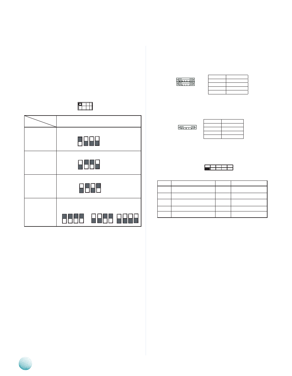
SW1/SW3 (on LEB-3110) and SW1/SW2/SW3/SW4/SW9/
SW10/SW11/SW112 (on LEK-COM08): These switches —
SW1, SW3 (on LEB-3110) and SW1, SW2, SW3, SW4, SW9,
SW10, SW11, SW12 (on LEK-COM08) — are used to adjust
the serial port type for COM1, COM2, COM3, COM4, COM5,
COM6, COM7, COM8, COM9, and COM10 respectively Use
the table below for the dip switch adjustment information
for COM1 through COM10
SW2/SW4 (on LEB-3110) and SW5/SW6/SW7/SW8/
SW13/SW14/SW15/SW16(on LEK-COM08)
These switches — SW2, SW4 (on LEB-3110) and SW5,
SW6, SW7, SW8, SW13, SW14, SW15, and SW16 (on
LEK-COM08)— are used to enable or disable the signal
termination for COM1, COM2, COM3, COM4, COM5, COM6,
COM7, COM8, COM9, and COM10 respectively Look
up at the last row of the above table for the dip switch
adjustment in this aspect for COM1 through COM10 We
strongly recommded that you disable termination when
the port is configured as RS-232 and enable it when the
port is configured as RS-485/RS-422
USB Port 1-2 Connector (USB1): These external USB type
A connectors comply with USB2 0 and support up to 480
Mbps connection speed
USB DIP PCB Connector (J9): An optional internal USB
2 0 type A connector
Serial Interface Connectors for COM11 and COM 12
(J4, J5): It is for connecting the RS-232 serial port module
cable
VGA Connector(VGA1):
The VGA is provided by the integrated GPU which
implements Intel® Graphics Media Accelerator 3150 which
supports the following features:
Contains a refresh of the third generation graphics
1
core
Intel
2
® Dynamic Video Memory Technology support
4 0
Directx 9 compliant Pixel Shader* v2.0••
3
500MHz render clock frequency••
4
Analog RGB displayoutput resolution up to 2048 *
5
1536 @ 60Hz
Intel
6
® Clear Video Technology including MPEG2
Hardware Acceleration and ProcAmp
COM Port No.
Port Type
COM 1 through COM10
RS-232
The respective switch for each COM Port:
1 ON
2 OFF
3 OFF
4 OFF
RS-422
The respective switch for each COM Port:
1 OFF
2 ON
3 ON
4 OFF
RS-485
The respective switch for each COM Port:
1 OFF
2 ON
3 OFF
4 ON
Termination
(Enable for TX, RX/
Enable for RX only/
disable)
The respective switch for each COM Port:
Enable: TX, RX ON Enable: RX ON Disable: OFF
ON
OFF
1 2 3 4
Pin No.
Function
1
USB power
2
USB_DAT-
3
USB_DAT+
4
GND
1 2 3 4
4 3 2 1
Pin No.
Function
1
USB power
2
USB_DAT-
3
USB_DAT+
4
GND
PIN No.
Function
PIN No.
Function
1
Data Carrier Detect (DCD)
2
Data Set Ready (DSR)
3
Received Data (RxD)
4
Request To Send (RTS)
5
Transmitted Data (TxD)
6
Clear To Send (CTS)
7
Data Terminal Ready (DTR)
8
Ring Indicator (RI)
9
Signal Ground
10
9 7 5 3 1
10 8 6 4 2