Chapter 2, System information, Front connectors – Lanner LEC-7388S User Manual
Page 8
8
System Information
Chapter 2
Embedded and Industrial Computing
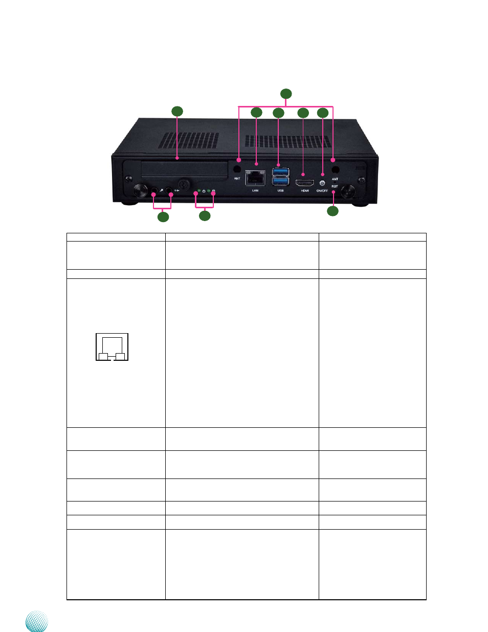
Front Connectors
Component
Description
Pin Definition Reference
F1 Hard Disk Slot
External 2.5” hard drive bay for easy access
and replacement of the data storage. It sup-
ports SATA 3.0 specification
F2 Antenna Hole
Reserved hole for 3G/Wi-Fi module antenna
F3 Gigabit Ethernet LAN port The LAN port is provided by Intel i217 Ethernet
controller which supports10/100/1000Mbps
connection speeds and PXE (Preboot
eXecution Environment). The LAN port LED
indicator is described below:
LINK/ACT (Amber)
On/Flashing: The port is linking and
•
active in data transmission.
Off: The port is not linking.
•
SPEED (Green/Yellow)
Yellow: The connection speed is
•
1000Mbps.
Green: The connection speed is 100Mbps
•
Off: .The connection speed is 10Mbps.
•
LAN1 on page 15
F4 USB 3.0 type A ports
Two USB 3.0 type A ports
USB1 on page 15
R5 HDMI Port
An HDMI port which supports both
4096x2304@24Hz (4K display) and
2560x1600@60Hz resolutions.
HDMI1 on page 14
F6 Power-on Button with
Dual LED
ATX power-on button with LEDs: stand-by
mode in red; power-on mode in green.
F7 Reset Button
A hardware reset button
F8 Mic-in Port/Line-out
Connect audio devices to these port.
MIC1/LINE1 on page 14
F9 HDD (Green) and
Power LED (Green)
HDD
Blinking: data access activities
•
Off: no data access activities
•
Power
On: The computer is on.
•
Off: The computer is off .
•
LINK/ACT
SPEED
F2
F7
F1
F6
F3
F4
F5
F8
F9