Controls and operation – Lanzar OPTIX User Manual
Page 3
- 2 -
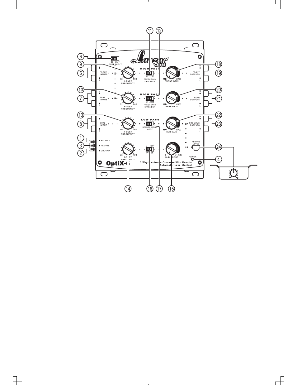
CONTROLS AND OPERATION
5. LEFT/RIGHT FRONT CHANNEL SIGNAL INPUTS: To be connected to the front channel output of the source
unit.
1.POWER INPUT TERMINAL(12V): To be connected to the positive terminal of your vehicle
battery or other constant +12V source.
2.GROUND INPUT TERMINAL: To be wired to the vehicle's chassis ground.
3.REMOTE TURN-ON INPUT TERMINAL(REMOTE): To be connected to the remote control wire or
antenna lead of the source unit for remote ON/OFF.
4. POWER INDICATOR: This indicator lights up when the internal switching power supply is activated and the
unit is operational.
Set to “IN” position the input signals coming in through the front channel signal inputs are split
and directed to the front and rear channels simultaneously. (This feature is to be engaged where
the source unit has no separate front, rear or subwoofer channel outputs)
If the source unit has independent front and rear channel outputs, disengage the parrel input by
sliding the switch to the “OUT” position
8. LEFT/RIGHT DUAL IN/OUT TERMINALS
As Input Terminal:To be connected to the subwoofer output of the source unit.
As Output Terminal:To be connected to the front channel input terminal of another electronic
crossover in a multi-crossover system.
7. LEFT/RIGHT REAR CHANNEL SIGNAL INPUTS: To be connected to the rear channel outputs of the source
unit. BUT MAKE SURE THAT THE DUAL INPUT SWITCH IS AT THE OUT POSITION.
6. DUAL INPUT SWITCH