Using ladj, Power supply requirements, Typical applications – Linx Technologies TXM-xxx-KH3 User Manual
Page 10
– –
– –
14
15
Using LADJ
The LADJ line allows the transmitter’s output power to be easily adjusted
for range control, lower power consumption, or to meet legal requirements.
This is done by placing a resistor between GND and LADJ. When LADJ is
connected directly to GND, the output power is at its maximum. Placing a
resistor lowers the output power by up to 7dB, as shown in Figure 12.
This is very useful during FCC testing to compensate for antenna gain
or other product-specific issues that may cause the output power to
exceed legal limits. A variable resistor can be used so that the test lab can
precisely adjust the output power to the maximum level allowed by law.
The resistor’s value can be noted and a fixed resistor substituted for final
testing. Even in designs where attenuation is not anticipated, it is a good
idea to place a resistor pad connected to LADJ and GND so that it can be
used if needed.
Power Supply Requirements
The module does not have an internal
voltage regulator; therefore it requires a
clean, well-regulated power source. While it
is preferable to power the unit from a battery,
it can also be operated from a power supply
as long as noise is less than 20mV. Power
supply noise can affect the transmitter
modulation; therefore, providing a clean
power supply for the module should be a
high priority during design.
A 10-ohm resistor in series with the supply followed by a 10µF tantalum
capacitor from V
CC
to ground will help in cases where the quality of supply
power is poor. These values may need to be adjusted depending on the
noise present on the supply line.
+
10
Ω
10
µF
Vcc IN
Vcc TO
MODULE
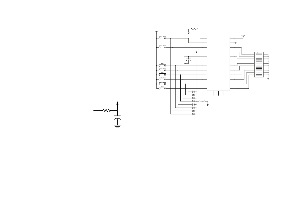
Typical Applications
Figure 21 shows an example of a basic remote control transmitter utilizing
the KH3 Series transmitter.
The data lines are connected to buttons. When a button is pressed it takes
the corresponding data line high and the TE line to begin the transmission
process. Since the data pins are internally pulled down to GND, no
pull-down resistors are needed.
Diodes are used to pull the TE line high when any data line goes high, while
isolating the data lines from each other. This makes the transmitter send
data when any button is pressed without affecting any of the other data
lines.
A ten-position DIP switch is used to set the address to either ground or
V
CC
. Since the address lines are internally pulled up to V
CC
, no pull-up
resistors are needed.
A resistor is placed on the LADJ line going to GND. This allows the
transmitter output power to be adjusted if needed.
+
100k
25
26
27
1
2
3
20
19
18
4
5
6
17
16
15
7
8
9
14
13
12
10
11
GND
GND
GND
VCC
VCC
GND
0 ohm
GND
LADJ/GND
1
D0
2
D1
3
GND
4
VCC
5
TE
6
D2
7
D3
8
D4
9
D5
10
D6
11
D7
12
A0
13
A1
14
A2
15
A3
16
A4
17
A5
18
A6
19
A7
20
A8
21
A9
22
GND
23
ANT
24
D_CFG
A_CFG0
A_CFG1
TXE-XXX-KH3
GND
Figure 20: Power Supply Filter
Figure 21: KH3 Series Transmitter Typical Application Circuit