Theory of operation, Compatibility with the kh2 series, Encoder operation – Linx Technologies TXM-xxx-KH3 User Manual
Page 8
– –
– –
10
11
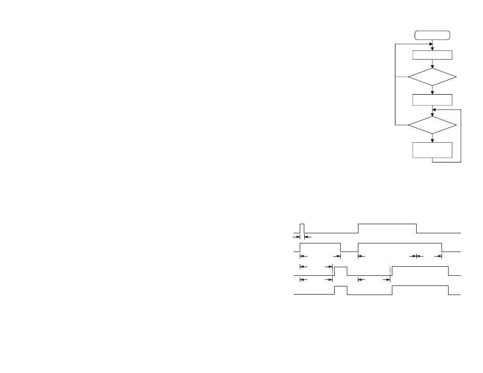
Encoder Operation
The KH3 Series transmitter internally utilizes
the DS Series encoder. The encoder begins
a three-word transmission cycle when the
Transmission Enable line (TE) is pulled high.
This cycle repeats itself for as long as the TE
line is held high. Once TE falls low, the encoder
completes its final cycle and then stops as
shown in the Encoder / Decoder Timing diagram
(Figure 16). When a transmission enable signal
is applied, the encoder scans and transmits the
status of the 10 bits of the address code and the
8 bits of the data serially in the order A0 to A9,
D0 to D7.
The state of address / data pins can be
interpreted as ONE, ZERO or OPEN bits,
following the logic of the D_CFG, A_CFG0 and
A_CFG1 inputs. See the Input Type Selection
section for more details. The open bit on the data
input is interpreted as logic low by the decoders since the decoder output
only has two states. The address pins are usually set to transmit particular
security codes by DIP switches or PCB wiring, while the data is selected
using push buttons or electronic switches.
Theory of Operation
The KH3 Series transmitter operation is straightforward. When the Transmit
Enable (TE) line is taken high, the on-board encoder IC is activated. The
encoder detects the logic states of the data and address lines. These
states are formatted into a 3-word transmission, which continues until the
TE line is taken low. The encoder creates a serial data packet that is used
to modulate the transmitter.
The transmitter section is based on a simple, but highly-optimized,
architecture that achieves a high fundamental output power with low
harmonic content. This ensures that most approval standards can be
met without external filter components. The KH3 Series transmitter is
exceptionally stable over variations in time, temperature, and physical
shock as a result of the precision SAW device that is incorporated as the
frequency reference.
The transmitted signal may be received by a Linx KH3 Series receiver
/ decoder module or a Linx LR Series receiver combined with the
appropriate decoder IC. Once data is received, it is decoded using a
decoder IC or custom microcontroller. The transmitted address bits are
checked against the address settings of the receiving device. If a match
is confirmed, the decoder’s outputs are set to replicate the transmitter’s
inputs.
Compatibility with the KH2 Series
The Legacy KH2 Series used encoders and decoders for Holtek® and the
KH3 migrates to the Linx DS Series encoder and decoder. The protocol
and functionality are compatible. There is some difference in the hardware
set-up for the address lines and the data lines. The legacy Holtek®
products used tri-state lines, so high, low and floating were each valid
states. The DS Series has bi-state lines; high and low only. Three lines
have been added to the KH3 module to allow for the selection of how the
address and data line states are interpreted. Please see the Input Type
Selection section for more details.
The KH3 transmitter has been designed to be compatible with legacy
systems. The module has been configured for the most common use of the
KH2 so that it can be placed on existing boards without modification. This
makes the KH3 a drop-in replacement for most applications.
Check
Check
< 1 Word
3 Words
Transmitted Continuously
3 Words
Decoder
Data Out
Decoder VT
Encoder
Data Out
Encoder
Transmit
Enable
2 Words
Power On
Standby Mode
Transmission
Enabled?
Yes
No
3 Data Words
Transmitted
Transmission
Still Enabled?
3 Data Words
Transmitted
Continuously
No
Yes
Figure 16: Encoder Flowchart
Figure 17: Encoder / Decoder Timing Diagram