Pin assignments, Pin descriptions, Module description – Linx Technologies TXM-xxx-KH3 User Manual
Page 7: Pin assignments pin descriptions, Rf stage encoder stage
– –
– –
8
9
Pin Assignments
Pin Descriptions
LADJ/GND
D0
D1
A9
A8
A7
A6
A5
A4
D2
GND
VCC
TE
D3
ANT
GND
1
2
3
4
5
6
7
8
17
18
19
20
21
22
23
24
D4
D5
D6
A1
A0
D7
A3
A2
9
10
11
12
13
14
15
16
25 26
27
D_CFG
A_CFG0
A_CFG1
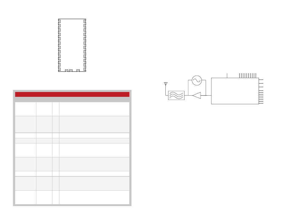
Figure 13: KH3 Series Transmitter Pin Assignments (Top View)
Figure 14: KH3 Series Transmitter Pin Descriptions
Pin Descriptions
Pin Number
Name
I/O Description
1
GND /
LADJ
—
Level Adjust. This line adjusts the output power level
of the transmitter. Connecting to GND gives the
highest output, while placing a resistor to GND lowers
the output level.
2, 3, 7, 8, 9,
10, 11,12
D0 to D1
I
Data Input Lines. When TE goes high, the module
encodes the state of these lines for transmission.
Upon receipt of a valid transmission, the receiver /
decoder replicates these lines on its output lines.
These lines are pulled to GND internally.
4, 23
GND
—
Analog Ground
5
V
CC
—
Supply Voltage
6
TE
I/O
Transmit Enable Line. When this line goes high, the
module encodes the states of the address and data
lines into a packet and transmits the packet three
times.
13, 14, 15,
16, 17, 18,
19, 20, 21, 22
A0 to A9
I
Address Lines. The state of these lines must match
the state of the receiver’s address lines in order for a
transmission to be accepted. These lines are pulled
to V
CC
internally.
24
ANT
—
50-ohm RF Output
25
D_CFG
I/O
Data Line Configuration. Determines whether a low
on a data line is interpreted as a zero bit or an open
bit. See the Input Type Selection section. This line is
pulled to GND internally.
26, 27
A_CFG0 /
A_CFG1
Address Configuration. These lines determine the
address bit type interpretation. See the Input Type
Selection section. A_CFG0 is pulled to GND and
A_CFG1 is pulled to V
CC
internally.
Module Description
The KH3 Series transmitter / encoder module combines a
high-performance Surface Acoustic Wave (SAW) based transmitter with an
on-board remote control encoder. When combined with a Linx KH3 Series
receiver / decoder, a highly reliable RF link capable of transferring control or
command data over line-of-sight distances of up to 3,000 feet is formed.
The module accepts up to 8 parallel inputs, such as switches or contact
closures, and provides ten address lines for creating unique transmitter
/ receiver relationships. The KH3’s compact surface-mount package
integrates easily into existing designs and is friendly to hand production or
automated assembly.
Output Isolation
& Filter
RF Amplifier
TX Enable
Keyed Output
SAW
Oscillator
50
Ω RF OUT
(ANT)
Parallel
Inputs
D0-D7
Address Inputs
A0-A9
RF STAGE
ENCODER STAGE
Data Out
D_CFG
D_CFG0
D_CFG1
Figure 15: KH3 Series Transmitter Block Diagram