Typical applications, Master development system – Linx Technologies RXM-GPS-R4 User Manual
Page 15
–
–
–
–
24
25
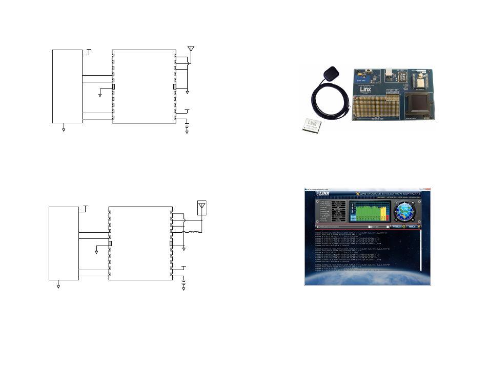
Typical Applications
Figure 27 shows the R4 Series GPS receiver in a typical application using a
passive antenna.
A microcontroller UART is connected to the receiver’s UART for passing
data and commands. A 3.3V coin cell battery is connected to the
VBACKUP line to provide power to the module’s memory when main
power is turned off.
Figure 28 shows the module using an active antenna.
A 300
Ω ferrite bead is used to put power from VOUT onto the antenna line
to power the active antenna.
Master Development System
The R4 Series Master Development System provides all of the tools
necessary to evaluate the R4 Series GPS receiver module. The system
includes a fully assembled development board, an active antenna,
development software and full documentation.
The development board includes a power supply, a prototyping area for
custom circuit development, and an OLED display that shows the GPS
data without the need for a computer. A USB interface is also included
for use with a PC running custom software or the included development
software.
The Master Development System software enables configuration of the
receiver and displays the satellite data output by the receiver. The software
can select from among all of the supported NMEA protocols for display of
the data.
Full documentation for the board and software is included in the
development system, making integration of the module straightforward.
Figure 29: The R4 Series Master Development System
Figure 30: The R4 Series Master Development System Software
NC
1
NC
2
1PPS
3
TX
4
RX
5
GND
21
NC
6
1PPS
7
/RESET
8
RFPWRUP
9
ON_OFF
10
GND 20
RFIN 19
GND 18
VOUT 17
NC 16
GND 22
NC 15
NC 14
NC 13
VCC 12
VBACKUP 11
µP
TX
RX
GND
VCC
GND
GND
VCC
GND
VCC
GND
300Ω
Ferrite Bead
Optional
OUT
IN
NC
1
NC
2
1PPS
3
TX
4
RX
5
GND
21
NC
6
1PPS
7
/RESET
8
RFPWRUP
9
ON_OFF
10
GND 20
RFIN 19
GND 18
VOUT 17
NC 16
GND 22
NC 15
NC 14
NC 13
VCC 12
VBACKUP 11
µP
TX
RX
GND
VCC
GND
GND
VCC
GND
VCC
GND
Optional
OUT
IN
Figure 27: Circuit Using the R4 Series Module with a Passive Antenna
Figure 28: Circuit Using the R4 Series Module with a an Active Antenna