Pin assignments, Pin descriptions – Linx Technologies TXM-xxx-LC User Manual
Page 6
Advertising
–
–
–
–
6
7
+8
+7
+6
+5
+4
+3
+2
+1
0
-1
-2
-3
-4
LADJ Resistor Value (
Ω)
51 100 150 200 240 300 360 430 510 560 620 680 750 820 910 1.1K
Output Power (dBm)
3V
5V
Pin Assignments
GND
DATA
GND
GND
ANT
LADJ/GND
GND
VCC
1
2
3
4
5
6
7
8
Pin Descriptions
Pin Number
Name
I/O Description
1
GND
—
Analog Ground
2
DATA
I
Digital Data Input
3
GND
—
Analog Ground
4
LADJ/GND
I
Level Adjust. This line is used to adjust
the output power level of the transmitter.
Connecting to ground gives the highest
output, while pacing a resistor to ground
lowers the output level (see Figure 9 on
5
ANT
—
50-ohm RF Output
6
GND
—
Analog Ground
7
V
CC
—
Supply Voltage
8
GND
—
Analog Ground
Pin Descriptions
Figure 9: Output Power vs. LADJ Resistor
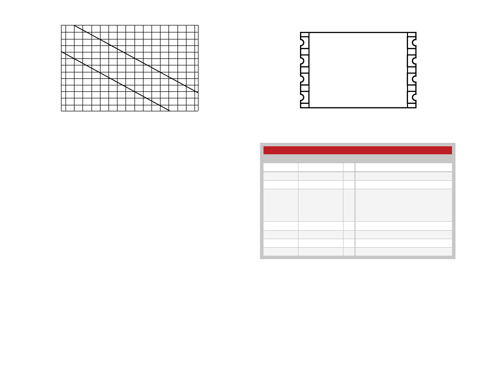
Figure 10: LC Series Transmitter Pinout (Top View)
Figure 11: Pin Descriptions
Advertising