Power supply requirements, Typical applications, Esd concerns – Linx Technologies TXM-xxx-LC User Manual
Page 9
–
–
–
–
12
13
Power Supply Requirements
The module does not have an internal
voltage regulator; therefore it requires a
clean, well-regulated power source. While
it is preferable to power the unit from a
battery, the unit can also be operated from
a power supply as long as noise is less than
20mV. Power supply noise can significantly
affect the transmitter modulation; therefore,
providing a clean power supply for the
module should be a high design priority.
A 10-ohm resistor in series with the supply followed by a 10µF tantalum
capacitor from VCC to ground will help in cases where the quality of supply
power is poor. These values may need to be adjusted depending on the
noise present on the supply line.
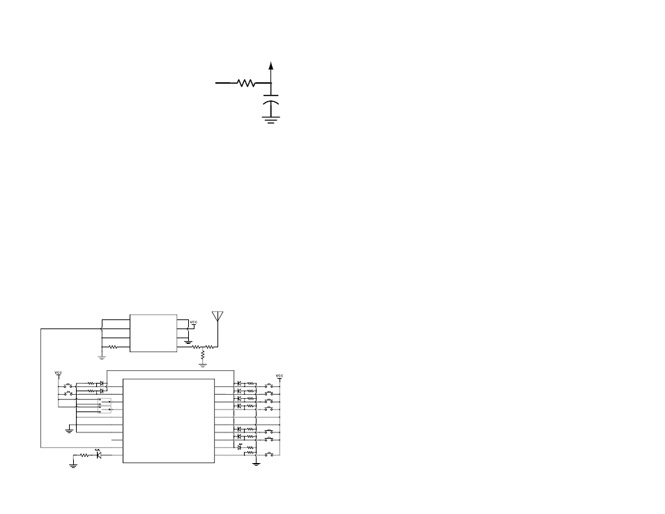
Typical Applications
The LC Series transmitter is ideal for the transmission of remote control /
command data. One of the easiest way to transmit on / off data or switch
closures is to use an encoder and decoder. These ICs provide a number
of data lines that can be connected to switches or buttons or even a
microcontroller. When a line is taken high on the encoder, a corresponding
line goes high on the decoder as long as the address matches. Figure 16
shows an example using the Linx MS Series encoder.
100k
100k
220
100k
100k
100k
100k
100k
100k
100k
LICAL-ENC-MS001
D6
D7
SEL_BAUD0
SEL_BAUD1
GND
GND
GND
TX_CNTL
DATA_OUT
MODE_IND
D5
D4
D3
D2
VCC
VCC
D1
D0
SEND
CREATE_ADDR
1
2
3
4
5
6
7
8
9
10
11
12
13
14
15
16
17
18
19
20
220
TXM-xxx-LC
1
2
3
4
5
6
7
8
GND
VCC
GND
ANT
GND
DATA
GND
LADJ/GND
750
0
0
OPEN
This circuit uses the LC Series transmitter and the MS Series encoder to
transmit button presses. The MS Series has eight data lines, which are
connected to buttons that pull the line high when pressed. When not used,
the lines are pulled low by 100k-ohm resistors. The encoder begins a
transmission when the SEND line is taken high. Diodes are used to pull this
line high when any data line is pulled high while isolating the data lines from
each other.
The MS Series Encoder Data Guide explains this circuit and the many
features of the encoder in detail, so please refer to that document for more
information.
A 750-ohm resistor is used on the LADJ line of the transmitter to reduce
the output power of the transmitter. This is appropriate for some antennas,
but may need to be adjusted depending on the design. Typically, a
resistor pad is placed on the board and a potentiometer is used by the
FCC test lab to adjust the output power to the maximum legal limit. The
potentiometer value is measured and the closest standard value resistor is
placed for final testing.
If the level adjust resistor does not provide enough attenuation, a T-pad
attenuator can be placed between the transmitter and antenna. This is a
network of three resistors that provides a set amount of attenuation while
maintaining a 50-ohm match between the antenna and the transmitter.
Application Note AN-00150 gives the formulas for calculating the resistor
values. If not needed, the series resistors can be zero ohms or shorted and
the parallel one not placed.
ESD Concerns
The module has basic ESD protection built in, but in cases where the
antenna connection is exposed to the user it is a good idea to add
additional protection. A Transient Voltage Suppressor (TVS) diode, varistor
or similar component can be added to the antenna line. These should have
low capacitance and be designed for use on antennas. Protection on the
supply line is a good idea in designs that have a user-accessible power
port.
Figure 16: LC Series Transmitter and MS Series Encoder
+
10
Ω
10
µF
Vcc IN
Vcc TO
MODULE
Figure 15: Supply Filter