Initial setup, The prototyping area – Linx Technologies MDEV-GPS-SG User Manual
Page 3
Page 3
INITIAL SETUP
Unpack the development system and install the AAA and coin-cell batteries.
Connect the external GPS antenna. The power switch can select between the
battery pack / DC power jack or USB if the board is plugged into a USB bus. To
use the display, turn the OLED display power switch on. The development board
is now ready for use. After turning on the power, the module will determine its
current position. Please note, the time required for an initial fix or after long
periods of storage will be considerably greater than in subsequent operation.
Please refer to the module’s data guide for complete information regarding time-
to-first-fix (TTFF). To protect the display and extend its life, turn the display off
before turning the board off.
THE PROTOTYPING AREA
In addition to its evaluation functions, the board may also be used for actual
product development. It features a prototyping area to facilitate the addition of
application-specific circuitry. The prototyping area contains a large area of plated
through-holes so that external circuitry can be placed on the board. The holes
are set at 0.100” on center with a 0.040” diameter, making it easy to add most
industry-standard SIP and DIP packages to the board.
External circuitry can be easily interfaced with the SG receiver through the
breakout header (J7) to the right of the prototyping area. A jumper shunt has
been provided to control the routing of data into the GPS module. By default the
jumper is set for operation with the on-board USB module. When communicating
with the GPS module using your own components this jumper shunt should be
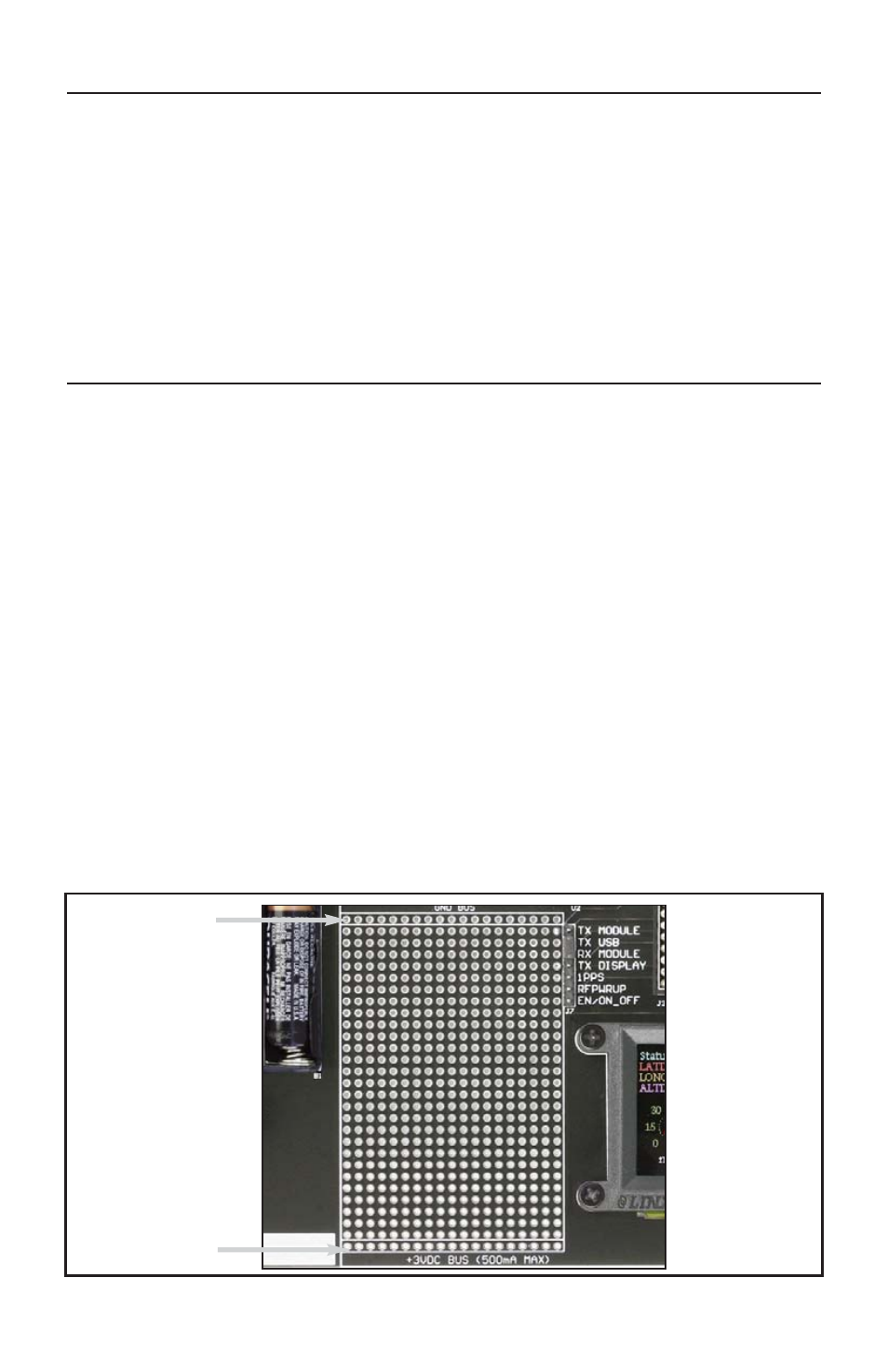
removed. At the bottom of the prototyping area is a row connected to the 3V
power supply and at the top is a row connected to ground.
NOTE: The on-board 3-volt regulator has approximately 300mA of headroom available for
additional circuitry. If added circuitry requires a higher current, the user must add an
additional regulator to the prototype area or power the board from an external supply.
Ground Bus
+3 Volt Bus
Figure 2: The Development Board Prototyping Area