Linx Technologies MDEV-GPS-SG User Manual
Page 4
Page 4
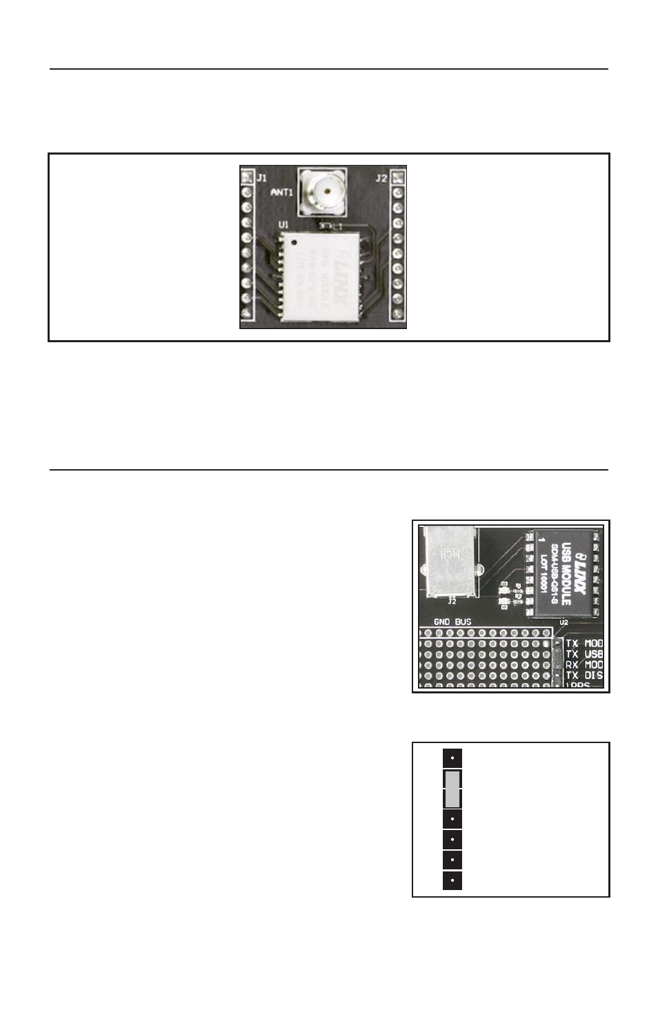
THE GPS RECEIVER SECTION
The receiver module is mounted on a daughter board which plugs into headers
on the main development board. This daughter board has an SMA antenna
connector to allow the attachment of many different styles of GPS antennas.
On the bottom of the main board is a CR2032 coin cell battery that provides
power to the RTC and SRAM when the receiver is powered down. This allows
the receiver to start up and obtain a position fix faster. This cell will provide about
two years of operation.
THE USB SECTION
The development board features a Linx QS Series USB module for interface to
a PC. This allows the board to be used with the supplied development software
or with custom software developed by the user.
Drivers for the USB module are included on the
software CD in the kit or may be downloaded
from www.linxtechnologies.com. Additional
information on using the QS Series USB module
can also be found on the website.
The USB connection also allows the board to be
powered by the USB bus instead of batteries.
This can be convenient during development to
eliminate the need for frequent battery
replacement.
Output data from the GPS module is connected
directly to the USB module, but data into the GPS
module is split. This is to prevent data collisions
between the USB module and any circuitry added
to the prototyping area. To route serial data from
the USB module to the serial data receive line on
the GPS module, use the supplied jumper to
connect the TX USB and RX MODULE lines on
the breakout header as shown in the adjoining
diagram. Remove this jumper for use with
external circuitry. The pin marked TX DISPLAY is
for Linx use and should be left unconnected.
TX MODULE
TX USB
RX MODULE
TX DISPLAY
1PPS
RFPWRUP
EN/ON_OFF
Figure 5: Jumper Configuration
Figure 4: The USB Section
Figure 3: The Development Board GPS Receiver Section