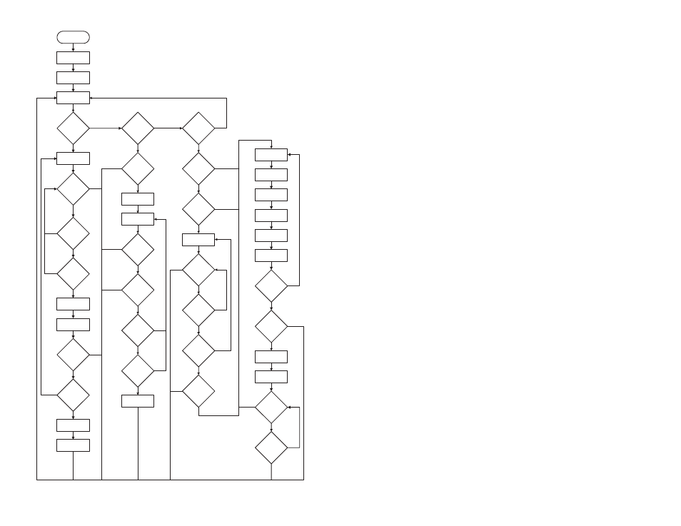
Typical system setup, Figure 12: hs series encoder flowchart – Linx Technologies LICAL-ENC-HS001 User Manual
Page 12
– –
– –
18
19
Power Up
NO
YES
Set Baud Rate
NO
YES
Is The
SEND Line
High?
Go To Sleep &
Wake On Interrupt
Is The
KEY_IN Line
High?
Pull The TX_CNTL
Line low
Is The
CREATE_PIN
Line High?
YES
NO
Time Out?
Set Timer
YES
NO
Is The
KEY_IN Line
High?
Is The
Data Valid?
Pull The TX_CNTL
Line High
YES
YES
NO
NO
Get Data
Is The
Data Valid?
YES
Did
Send And
Receive
Confirmation
Pass?
Save Data
Pull MODE_IND
High For 1 Second
YES
NO
NO
Is PIN
Active?
YES
NO
Set 15-Second
Timer
Toggle
MODE_IND Line
15 Second
Timer Time
Out?
YES
NO
Is The
CREATE Line
High?
YES
NO
Was The
4th Button
Pressed?
Save PIN
YES
NO
Is PIN
Enabled?
Set Timer To 2S
YES
NO
Is PIN
Active?
YES
NO
Did The Timer
Expire?
YES
NO
YES
NO
Was A Button
Pressed?
YES
NO
Was The
4th Button
Pressed?
Does PIN
Match?
YES
NO
Pull The DATA
Line High
Get Data Byte
Create Packet
Pull The DATA
Line Low
Send Packet
NO
YES
Is The
SEND Line
High?
Pull The TX_CNTL
Line High
Is PIN
Enabled?
Set Timer From
SEL_TIMER Line
NO
YES
Did The Timer
Expire?
NO
YES
Was A Button
Pressed?
NO
YES
Is The
SEND Line
High?
NO
YES
Pull The TX_CNTL
Line Low
Figure 12: HS Series Encoder Flowchart
Typical System Setup
The HS Series offers an unmatched combination of features and security,
yet is easy for system designers and end users to operate. The following
demonstrates a typical user setup followed by more detailed design
information. The Typical Applications sections of the encoder and decoder
data guides show the circuit schematics on which these examples are
based.
1. Create and exchange a key from a decoder to an encoder.
The high security key is created and exchanged by placing the decoder
in the Create Key Mode. The decoder’s MODE_IND line LED lights to
indicate that the decoder has entered Create Key Mode. The decoder’s
CREATE_KEY button is then pressed ten times to create the key. After
the tenth press, the MODE_IND LED turns off and the decoder sends
the key out of the KEY_OUT line. The MODE_IND LED on the encoder
lights to indicate that the key has been successfully transferred.
2. Establish Control Permissions
The user establishes what buttons on the encoder are recognized by
pressing the decoder's LEARN button. The decoder’s MODE_IND
LED starts flashing and the user presses the buttons that are allowed
access. Control Permissions are stored when the LEARN button is
pressed again or automatically after 17 seconds.
There are other powerful options such as programming a user PIN or
copying a decoder but these simple steps are all that is required for a
typical setup. It is really that simple for a manufacturer or end user to setup
the product!