Pin assignments – Linx Technologies LICAL-ENC-HS001 User Manual
Page 5
– –
– –
4
5
Pin Descriptions
Pin Number
Name
I/O
Description
1, 2, 13, 14,
17–20
D0–D7
I
Data Input Lines. The state of these lines are
captured when the SEND line goes high and
encrypted for transmission. Upon successful
reception, these states are reproduced on the
outputs of the decoder.
3
SEL_BAUD
I
Baud Rate Selection Line. This line is used to
select the baud rate of the serial data stream. If
the line is high, the baud rate is 28,800bps, if it
is low, the baud rate is 4,800bps. The baud rate
must be set before power up. The transcoder
will not recognize any change in the baud rate
setting after it is on.
4
SEL_TIMER
I
PIN Time-Out Timer Select Line. This line is
used to set the length of inactive time before
PIN reentry is required.
5, 6
GND
Ground
7
KEY_IN
I
Key Input Pin. This line is used to input the key
from the decoder.
8
TX_CNTL
O
External Transmitter Control Line. This line
goes high when the SEND line goes high and
low when the SEND line goes low. This can be
used to power up external devices, such as a
transmitter, when the encoder is sending data,
and power it down when the encoder is asleep.
It can also be used to drive a LED for visual
indication of transmission.
9
DATA_OUT
O
Serial Data Output. The encoder outputs
an encrypted serial data stream on this line.
This line can directly interface with all Linx
RF transmitter modules or it can be used to
modulate an IR diode.
10
MODE_IND
O
Mode Indicator Output. This line activates while
the encoder is in Get Key Mode or Create Pin
Mode. It allows the connection of a LED or
other indicator for user feedback.
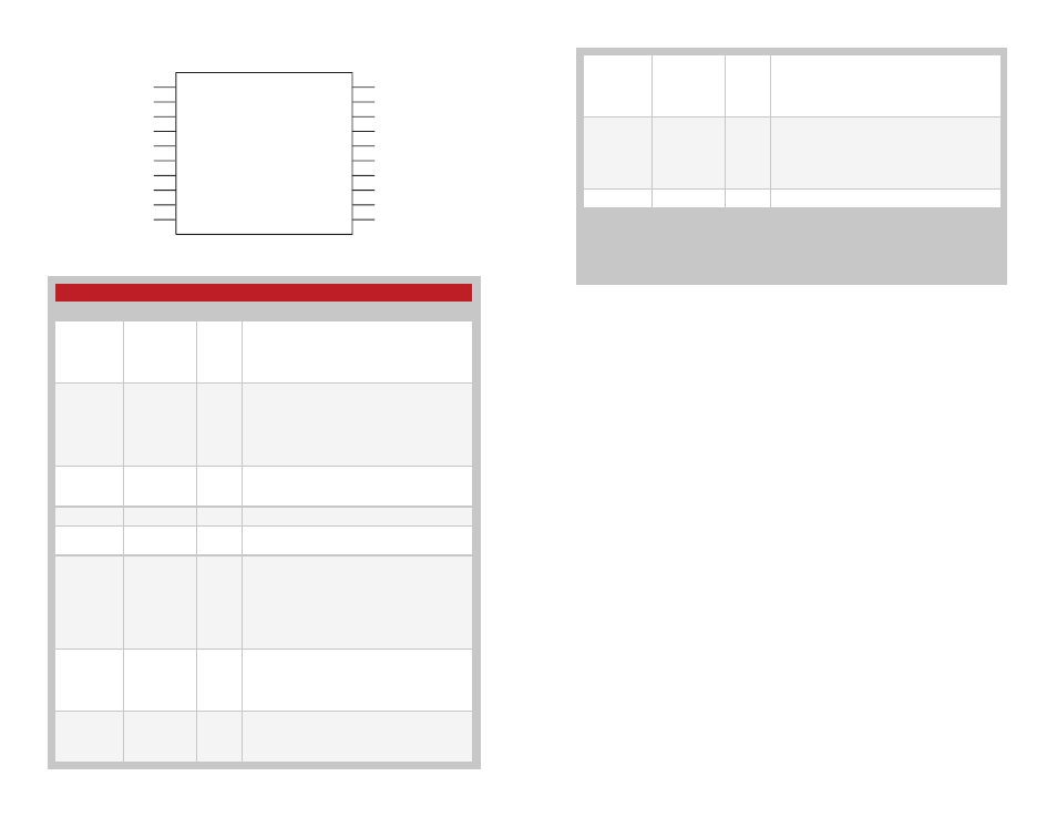
Pin Assignments
Figure 6: HS Series Encoder Pin Assignments
LICAL-ENC-HS001
D6
D7
SEL_BAUD
SEL_TIMER
GND
GND
KEY_IN
TX_CNTL
DATA_OUT
MODE_IND
D5
D4
D3
D2
VCC
VCC
D1
D0
SEND
CREATE_PIN
1
2
3
4
5
6
7
8
9
10
11
12
13
14
15
16
17
18
19
20
11
CREATE_PIN
I
Create PIN Mode Selection Line. When this line
is taken high, the encoder enters Create PIN
Mode and allows the user to set a Personal
Identification Number (PIN) to control encoder
access.
12
SEND
I
Encoder Send Data Line. When this line goes
high, the encoder records the states of the
data lines, encrypts them for transmission, and
sends the packet as a serial bit stream through
the DATA_OUT line at the baud rate selected by
the state of the SEL_BAUD line.
15, 16
V
CC
Supply Voltage
None of the input lines have internal pull-up or pull-down resistors. The input lines must
always be in a known state (either GND or V
CC
) at all times or the operation may not be
predictable. The designer must ensure that the input lines are never floating, either by us-
ing external resistors, by tying the lines directly to GND or V
CC
, or by use of other circuits
to control the line state.
Figure 7: Pin Descriptions