Dust and chip extraction, Clamping the work piece, Horizontal mitre angle – Powerplus POWXQ5335 TELESC. MITRE SAW 1800W 254MM EN User Manual
Page 8: Adjustment of the saw blade and guide rail, Vertical bevel angle, Adjustment of the saw blade and the base
POWXQ5335
EN
Copyright © 2014 VARO
P a g e
| 8
www.varo.com
9.2
Dust and chip extraction
For integrated dust extraction, place the dust bag (20) on the sawdust ejector.
For external dust, you can use a vacuum cleaner hose.
The dust bag is only for a partial dust removal! It is designed to break the
dust extraction.
9.3
Clamping the work piece
Make sure the work piece can’t be catapulted. The clamp(12) is the most perfect gadget to
avoid this.
Press the work piece against the fence (4) and between the clamp
Tighten the clamp (12) clockwise to secure the work piece.
9.4
Horizontal mitre angle
The horizontal mitre angle can be set in the range from -45° to 45°. The horizontal mitre angle
scale shows the currently set in degrees.
Loosen the locking knob (6) at the top of the guide rail.
Push the lever (6).
Rotate the saw table (5) to the required angle ( to the right or to the left). The required
angle can be read of the scale flute (8).
Tighten the locking knob (6) clockwise.
9.5
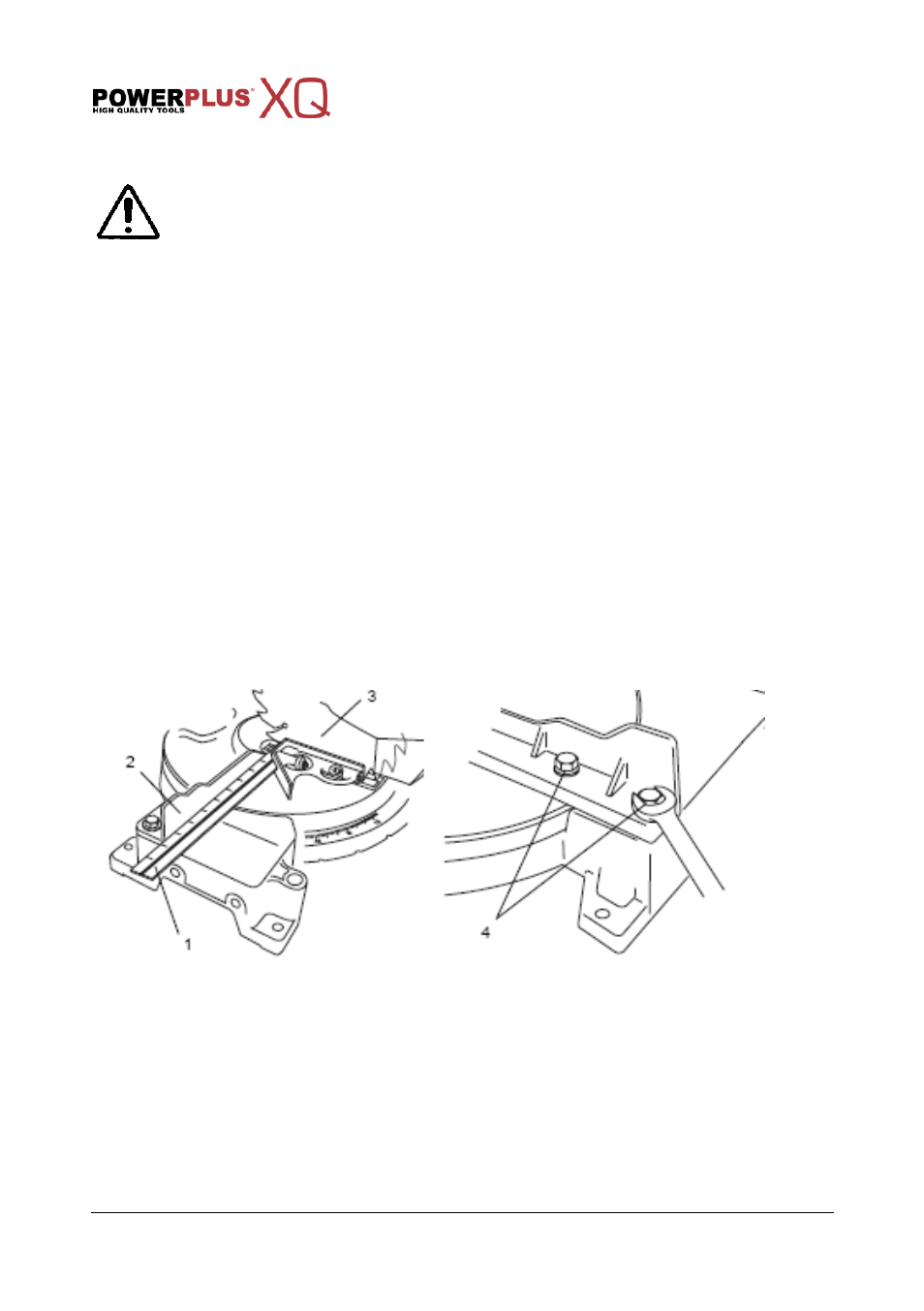
Adjustment of the saw blade and guide rail.
Position the saw in the lower position and block it with the blocking pin.
Now hold the try square (90°) against the guide rail and the saw blade. The latter must
make complete contact with the try square. If this is not the case, then you can adjust the
angle by moving the guide rail. To carry out this step, use the delivered key for loosening
the screws. Do not forget to re-tighten the screws afterwards.
9.6
Vertical bevel angle
The vertical bevel angle can be set in the rang of 0° to 45°. The vertical bevel scale shows the
currently set in degrees.
Loosen the locking lever(22), if tightened.
Swing the tool arm (15) with the handle (18) to the required angle.
Tighten the locking lever (22).
9.7
Adjustment of the saw blade and the base
Position a try square against the saw blade and the sawing table.
If the saw blade is not completely in line, then you can adjust the angle by means of the
screw.
After this, you can adapt the zero position on the graduated scale.