Fig.1, Introduction & specification, Compressor preparation – Sealey SA0615KIT User Manual
Page 2: Compressor operation
2. IntRoDuctIon & specIFIcAtIon
Kit comprises sa0615 6ltr compressor, 5mtr air hose and nail/staple gun. compressor is also suitable for use with the sealey range of tyre
inflators and air brushes. compressor fitted with twin gauges displaying tank and working pressures. features four anti-vibration rubber feet for
added stability when in use.
3. compRessoR pRepARAtIon
WARnIng! the compressor is supplied with synthetic lubricating oil in the pump - see para. 5.4.
3.1.
remove compressor from packaging and inspect for any shortages or damage. If there are any problems contact your supplier.
3.2.
confirm that the mains voltage corresponds with the voltage shown on the compressor data plate.
3.3.
the compressor should be installed on a flat surface, or one that does not exceed 10
° either transversely or longitudinally, and should
be in a position that allows good air circulation around the unit with at least 100cm between it and any other objects.
3.4.
ImpoRtAnt! Remove the oil dipstick from the pump (fig.2), wipe it clean, re-insert it and then remove it and check that the
oil level is correct (fig.3). Add oil if required until the level is correct. Replace the dipstick.
Do not Attempt to Run the compRessoR untIl thIs hAs Been checkeD.
3.5.
take care when selecting tools for use with the compressor. Air tool manufacturers normally express the volume of air
required to operate a tool in cubic feet per minute (cfm). this refers to free air delivered by the compressor (‘air out’) which
varies according to the pressure setting. Do not confuse this with the compressor displacement which is the air taken in by
the compressor (‘air in’). ‘Air out’ is always less than ‘air in’ - due to losses within the compressor - so it is important that
before choosing equipment, the correct Air Displacement figures are adhered to.
7
Do not operate the compressor if you are tired or under the influence of alcohol, drugs or intoxicating medication.
7
Do not use this compressor to perform a task for which it is not designed.
7
Do not deface the certification plate attached to the compressor tank.
DANGER! DO NOT direct the output jet of air towards people or animals.
7
Do not operate the compressor without an air filter.
7
Do not allow anyone to operate the compressor unless they have received full instruction.
WARnIng! The air tank is a pressure vessel and the following safety measures apply:
7
DO NOT tamper with the safety valve and DO NOT modify or alter the tank in any way and DO NOT strap anything to the tank.
7
DO NOT subject the tank to impact, vibration or to heat and DO NOT allow contact with abrasive or corrosive materials.
3
DO drain condensation from tank daily and inspect inside walls for corrosion every three months. Have a detailed tank
inspection carried out annually. The tank shell must not fall below the certified thickness at any point.
WARnIng! If an electrical fuse blows, ensure that it is replaced with one of identical type and rating.
3
When not in use, disconnect from the mains, vent the tank and store the compressor in a safe, dry, childproof location.
When the compressor is not in use, it should be switched off, disconnected from the mains supply and the air drained from
the tank.
compressor
motor output: . . . . . . . . . . . . . . . . . . . . . . . . . . . . . . . . . . . . . 1.5hp
Voltage/phase: . . . . . . . . . . . . . . . . . . . . . . . . . . . . . . . . . 230V/1ph
current: . . . . . . . . . . . . . . . . . . . . . . . . . . . . . . . . . . . . . . . . . . 4.8a
Air displacement: . . . . . . . . . . . . . . . . . . . . . . . . . . . . . . . . 4.8cfm
max. free air delivery: . . . . . . . . . . . . . . . . . . . . . . . . . . . . . 3.4cfm
tank capacity: . . . . . . . . . . . . . . . . . . . . . . . . . . . . . . . . . . . . . . 6ltr
max pressure: . . . . . . . . . . . . . . . . . . . . . . . . . . . . . . . 116psi/8bar
noise level: . . . . . . . . . . . . . . . . . . . . . . . . . . . . . . . . . . . . .95dB.a
nail/staple gun
maximum pressure: . . . . . . . . . . . . . . . . . . . . . . . . .120psi/8.3bar
operating pressure: . . . . . . . . . . . . . . . . . . . 70-110psi/4.8-7.6bar
Weight: . . . . . . . . . . . . . . . . . . . . . . . . . . . . . . . . . . . . . . . . . . 1.2kg
staple capacity: . . . . . . . . . . . . . . . . . . . . . . . . . 16-40mm 18sWG
nail capacity: . . . . . . . . . . . . . . . . . . . . . . . . . . . 16-50mm 18sWG
4. compRessoR opeRAtIon
WARnIng! ensuRe thAt You hAVe ReAD, unDeRstooD AnD
ApplIeD sectIon 1 sAFetY InstRuctIons.
note: DutY cYcle: this is a 70% duty cycle air compressor. do not run the
air compressor for more than approximately 40 minutes in any one hour.
doing so could damage the compressor.
4.1.
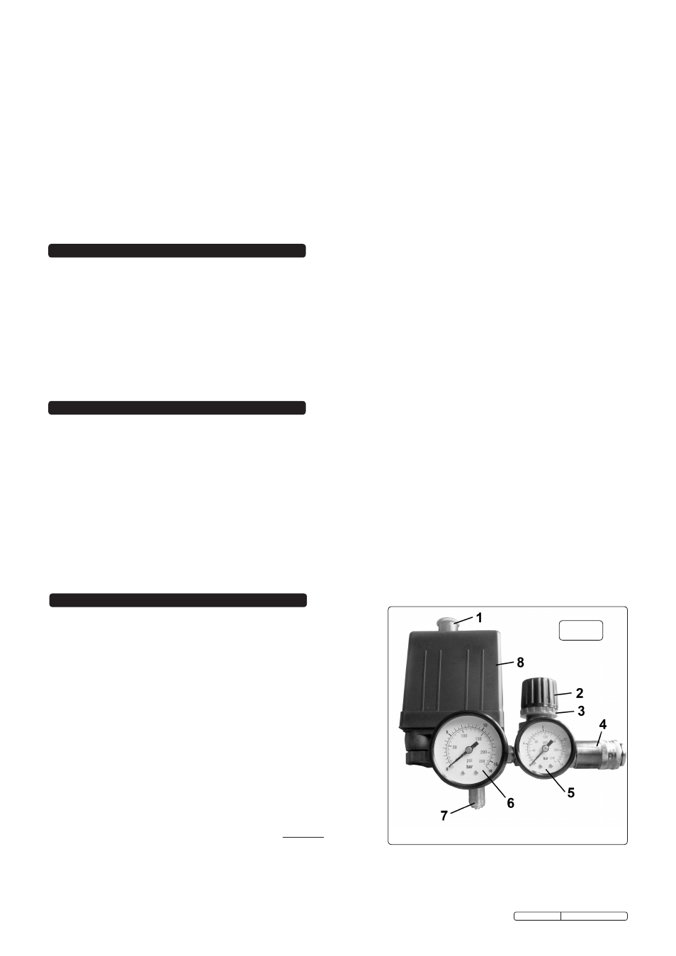
make sure that the main switch (fig.1.1) is ‘off’ (pushed down).
4.2.
check the oil level by checking the dipstick (figs.2 and 3).
4.3.
ensure that the tank drain valve is closed (fig.5).
4.4.
ensure that the outlet pressure regulator is not at full pressure (fully
clockwise), if it is, turn the knob anti-clockwise a few turns (fig.1.2).
4.5.
connect the required air tool to the compressor via an air line connected
to the air outlet (fig.1.4).
4.6.
Plug the mains cable into the mains supply and start the compressor by
pulling up the main switch into the 'on' position (fig.1.1).
4.7.
allow the pressure in the tank to rise to the maximum at which point the
compressor will automatically cut out. tank pressure is shown on the
larger gauge (fig.1.6).
4.8.
Begin to gradually increase the pressure regulator by turning the knob
clockwise until the small gauge registers the required operating
pressure specified for the tool connected. always
adjust up to the
required pressure rather than down from a higher pressure. the required
setting, once achieved, can be locked by screwing the locking ring (fig.1.3) up tight underneath the adjusting knob.
4.9.
commence using the air tool. the compressor will operate automatically, cutting in and out as required to restore the air pressure
in the tank. the pressure switch (fig.1.8) stops the motor when the maximum tank pressure is reached and restarts it when pressure
falls below the minimum threshold - approximately 2 bar (29psi) less than the maximum pressure.
fig.1
Original Language Version
sa0615KIt Issue: 2- 20/02/12