Sealey TBB300 User Manual
Page 2
TBB300 Issue No.1 17/11/11
Original Language Version
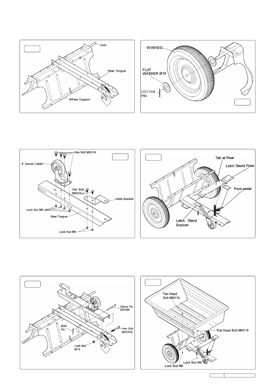
fig.3
fig.4
fig.5
fig.6
fig.7
fig.8
4.1.3 Lay the rear tongue (open side facing up) onto the Wheel
Support. Assemble the axle through the wheel support and the
tongue as indicated in fig.3.
4.3 Assemble a wheel to each end of the axle (with the valve stem
facing outwards). Ensure that a washer is placed either side of
each wheel. Retain the wheels with a Ø3x25 cotter pin
through each end of the axle.
4.2 Assemble the hitch bracket to the front tongue using two sets
of M8x20mm hex bolts with M8 lock nuts as shown in fig.4.
4.2.1 Assemble the 4" swivel castor to the front tongue using 4
M6x16 hex bolts and M8 lock nuts. See fig.4. Tighten fixings.
4.2.2 Place the front tongue inside the rear tongue as shown in fig.5.
fasten the tongues together using an M10x95 bolt and a
10mm lock nut. Do not overtighten the nut as this bolt acts as a
pivot between the front and rear tongue.
4.2.3 Insert a clevis pin Ø13x98 through both tongues and secure
with an 'R' pin Ø3 as shown in fig.5.
4.3.1 Turn the wheel support over to rest on the wheels. Place the
latch stand bracket onto the tongue sliding it underneath the
foot pedal notch. Orientate the latch stand plate as shown in
fig.7. The tabs at the end of the channels must face to the rear.
Place the latch stand plate down onto the latch stand bracket
as shown in fig.7.
4.3.2 Place the poly tray down onto the wheel support and the latch
stand plate. fasten the tray to the wheel support using eight
M8x16 flat head bolts and M8 lock nuts. fasten the tray to the
latch stand plate and latch stand bracket using four M6x16 flat
head bolts and M6 lock nuts as shown in fig.8. Do not fully
tighten yet.