Fig.4 fig.5 fig.6, Operation – Sealey SAC82425VLN User Manual
Page 3
wArNiNG! Ensure that you have read, understood and apply section 1 safety
instructions.
imporTANT. the use of extension leads to connect this compressor to the mains is
not recommended as the resulting voltage drop reduces motor, and therefore pump,
performance and could cause damage to your compressor.
imporTANT
the motor on this compressor is 2.5HP/230V and at normal mains voltage will start
within the capacity of a 13Amp fused circuit.
certain local conditions relating to electrical supply in the uK can result in the voltage
varying between a low of 216Volts and a high of 253Volts and at such times the 13
Amp fuse in the compressor plug may blow. this is normal and is not a fault with the
compressor. However if it happens regularly we recommend that you consult an
electrician with a view to installing a 16Amp supply, with contact breaker, to avoid the
inconvenience of frequent fuse replacement. if using an extension lead ensure that
cable size is at least 2.5mm². Ensure cable is fully unwound.
imporTANT
take care when selecting tools for use with the compressor.
Air tool manufacturers normally express the
volume of air required to operate a tool in cubic feet per
minute (cfm). this refers to free air delivered by the
compressor (‘air out’) which varies according to the
pressure setting. Do not confuse this with the
compressor displacement which is the air taken in by
the compressor (‘air in’). ‘Air out’ is always less than
‘air in’ and so it is important that, before choosing
equipment, you study the ‘free Air Delivery’ figures
shown in specifications, section 2.
4.1
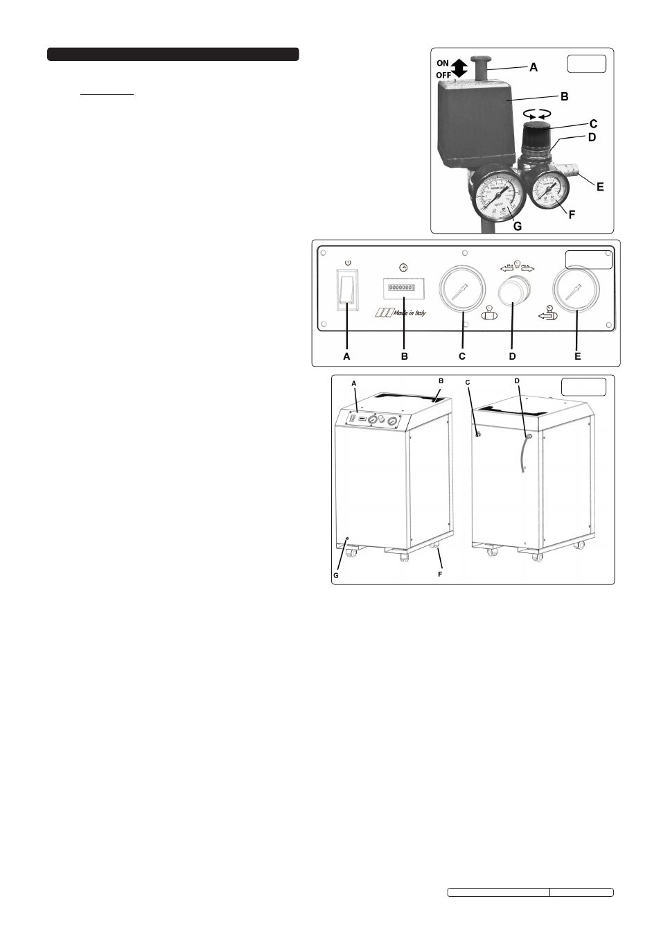
sTArTiNG THe compressor.
4.1.1
sAc89025vLN is fitted with a push/pull type of on/off
switch (fig.4A). to turn the compressor ‘on’ pull the
switch knob upwards. to turn the compressor ‘off’ push the
switch knob downwards.
sAc82425vLN is fitted with a rocker type of on/off switch
(fig.5A). to turn the compressor 'on' push the switch to 'i' to
turn the compressor 'off' push the switch to 'o'.
4.1.2 check that the on/off switch is in the “off” position and the
regulator tap (fig4.c & fig.5D) is closed (Zero ‘0’ bar,
Anti-clockwise).
4.1.3 Plug mains lead into mains supply and start the compressor by
turning it on.
4.1.4 start the compressor and leave the compressor running with
the regulator tap (fig.4c & fig.5D) set to maximum pressure.
make sure that the pressure in the tank rises and that the
compressor stops automatically when the maximum pressure
value allowed - written on the specification plate and shown on
the gauge (fig.4G & fig.5c) - is achieved. the compressor will
now operate automatically. the pressure switch stops the
motor when the maximum tank pressure is reached, and will
restart it when pressure falls below the minimum threshold -
approx. 2bar (29psi) less than the maximum pressure.
4.1.5 stop the compressor by pushing the rocker switch to 'o' or
pushing the switch downwards (fig.4A & fig.5A). the compressed air inside the compressor head will flow out, making the restart
easier and preventing the motor from being damaged.
Do NoT, other than in an emergency, stop the compressor by switching off the mains socket, or by pulling the plug out of the socket,
as the pressure relief will not then occur and motor damage may result upon restart.
When the compressor runs correctly and is stopped correctly there will be:
(a) a whistle of compressed air when the motor stops,
(b) a protracted whistle (about 20-25 seconds) when the compressor starts with no pressure in the tank.
4.1.6 the output pressure is regulated by the pressure regulator tap (fig.4c & fig.5D). turn the tap clockwise to increase pressure and
anti-clockwise to reduce it. the tap can be locked at any required setting by tightening the locking ring up against the underside of
the tap. to determine the correct working pressure for any piece of equipment check the corresponding manual. When the compressor
is not being used, set the regulated pressure to zero so as to avoid damaging the pressure reducer.
NoTe: a) if the motor does not cut in and out, but runs continuously when using an air appliance, the capacity of the compressor may be too
small for the equipment or tool.
b) the gauges on the left (fig.4G & fig.5c) indicates the pressure inside the main tank. the gauges on the right (fig.4f & fig.5E)
indicate the pressure supplied to the air equipment.
should the pressure in the main tank exceed the pre-set switch maximum, the safety valve will activate.
wArNiNG! For this reason Do NoT tamper with, or adjust, the pre-set switch or safety valve.
4. operATioN
fig.4
fig.5
fig.6
Original Language Version
sAc89025VLn, sAc82425VLn issue: 2 - 22/02/12