Fig.10, Fig.9, Maintenance (engine) – Sealey PWM2500 User Manual
Page 4: Maintenance (washer)
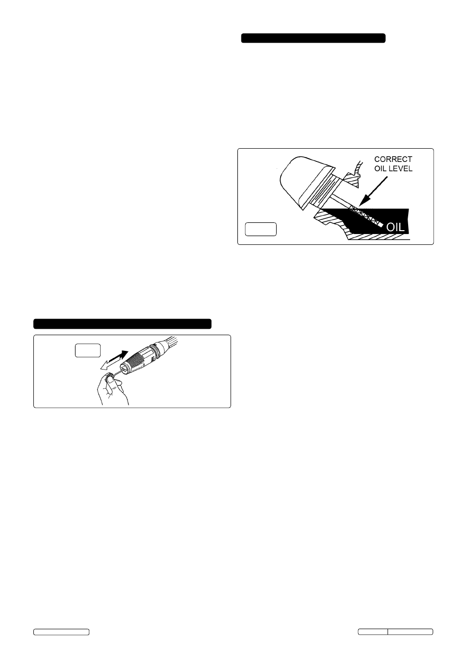
fig.10
7.2 CHECKING THE OIL LEVEL. ensure the unit is on a level
surface.
7.2.1.Unscrew the dipstick and wipe it clean of oil. Note that the
maximum oil level should be just below the opening of the filler
neck.
7.2.2 .Check the oil level by seating the dipstick into the hole without
screwing it in. See fig.8 above. If there is no oil on the dipstick
when it is removed the level is too low and should be topped
up immediately with an SAe10W - 30 oil.
7.2.3 .Top up oil if necessary and recheck level.
7.2.4 .Screw dipstick fully home to seal oil fill hole.
Note: The engine is fitted with a low oil sensor which will
automatically shut the engine down in a low oil situation. The
sensor may also operate if the unit is not on a level surface.
7.3 ENGINE STORAGE. If the unit is not to be used for more than
one month the following procedure should be followed.
7.3.1. Top-up engine oil to maximum.
7.3.2. drain petrol from the fuel tank, fuel line, fuel tap and carburettor.
7.3.3. Pour one teaspoon of engine oil through the spark plug hole, pull
the recoil starter several times and replace the spark plug. Then
pull the starter slowly until an increase in pressure is felt
indicating that the piston has commenced its compression stroke
and leave it in this position. This closes both the intake and
exhaust valves and prevents the inside of the cylinder from
rusting.
7.3.4. Cover the unit and store it in a clean dry place that is well
ventilated and away from open flame or sparks.
7.4. AIR CLEANER. The air cleaner is situated below the fuel tank
(see fig.2. To access the air cleaner elements, unclip the over-
centre clips at the top and bottom and remove the black cover to
reveal the foam pads as shown in fig.11.
7.4.1. Remove the foam pads from the air cleaner housing.
7.4.2. Wash the foam pads with a household detergent or a high
flash-point solvent and squeeze dry.
7.4.3.Refit the two foam pads (coarse pad outermost) into the
location and bed down.
7.4.4. Replace air filter casing lid and secure with both over-centre
clips.
7. MAINTENANCE (ENGINE)
7.1 Change engine oil after the first 8 hours of operation.
Thereafter, change oil monthly or every 50 hours of operation.
Change oil more often if engine is operated under heavy load,
or in high ambient air temperatures. during normal operation,
partially burned fuel, small particles of metal from the cylinder
walls, pistons, bearings and combustion deposits will gradually
contaminate the oil. If the oil is not changed regularly, these
foreign particles can cause increased friction and a grinding
action which shortens the life of the engine. Fresh oil also
assists in cooling. Old oil gradually becomes thick and loses its
cooling ability as well as its lubricating qualities.
6. MAINTENANCE (WASHER)
5.3. CLEANING
5.3.1. Push nozzle forward - LOW PRESSURE - and rotate to fan jet.
Only apply detergent at the low pressure rate.
5.3.2. depress the trigger to apply the detergent to the dry surface
which is to be cleaned.
Vertical surfaces must be cleaned from the bottom upwards.
5.3.3. When detergent application is complete remove the syphon
tube from the detergent container and place it in a container
of clean water. Run the washer at low pressure to purge the
gun of detergent.
5.3.4. leave the detergent to act for 1-2 minutes, but
do not allow
the surface to dry.
5.3.5. Pull nozzle back - HIGH PRESSURE - and use fan or pencil
jet for washing.
5.3.6. Hold nozzle firmly at least 30cm (12”) from the surface and
commence washing with high pressure clean water. Work
from the bottom upwards, and avoid the water running on to
unwashed surfaces.
5.4.
SHUT DOWN PROCEDURE.
5.4.1. When you have finished washing, move the throttle lever to
the right to the slow running position.
5.4.2. Turn off the engine switch and close the fuel tap. Turn off the
mains water supply.
5.4.3. discharge residual pressure from the washer by pressing the
trigger until no more water comes out of the nozzle.
5.4.4. engage the trigger safety catch, wipe the washer and store in
a dry, safe, childproof area.
5.5. TRANSIT.
5.5.1. In the upright position the washer stands on four feet and the
two wheels are off the ground. The front feet have suckers
attached which help to eliminate creep. The rear feet are out
of sight between the wheels. To move the unit tip it backwards
on the rear feet until the wheels make contact with the
ground. Keep the unit well tipped back as you move it.
Maintenance should only be performed with the engine turned
off and the unit disconnected from the mains water supply.
6.1
Clean gun nozzle with a suitable rigid piece of wire (fig 7).
detach lance from gun, remove any dirt from the nozzle head
and rinse with clean water. If this does not improve the flow
from the nozzle it should be replaced.
6.2
Check and clean the water inlet filter every 50 operating
hours. The filter is moulded into a rubber washer. Unscrew
the brass connector from the black fitting on the water inlet on
the pump. Push the black fitting backwards which will
eject the filter/washer and then clean the filter washer. If the
filter is damaged in any way it should be replaced.
6.3
Check and clean the detergent filter at the end of the
detergent input tube on a regular basis.
6.4
WINTER STORAGE: Fill the pump with an antifreeze
mixture before storing in a frost free, safe, dry area for the
winter. Introduce the antifreeze by the following method.
6.4.1 Shut off the water supply and disconnect the supply hose.
Relieve pressure within the pump by squeezing the gun
trigger. Remove the high pressure hose and let all water drain
from it. Hold gun/lance with nozzle downwards and pull
trigger until all water has drained out.
6.4.2 disconnect the ignition lead from the spark plug.
6.4.3 Connect a short length of garden hose to the water inlet and
using a funnel pour an antifreeze mixture into it.
6.4.4 Pull the recoil starter several times to circulate the antifreeze
through the pump. Continue to add antifreeze and pull the
recoil until antifreeze is expelled from the pump.
fig.9
Original Language Version
PWM2500 Issue: 1 - 08/05/13
© Jack Sealey limited