Fig.4 fig.5, Fig.3, Introduction & specification – Sealey TP6905 User Manual
Page 2
2.
INTRODUCTION & SPECIFICATION
6 and18ltr capacity devices constructed from composite materials and suitable
for extraction of all types of engine, transmission and lubricating oils from cars,
motorcycles, marine engines, stationary engines and industrial machinery.
features a controlled discharge function for emptying the unit. suitable also for
low viscosity fluids such as water. supplied with Ш5.8, Ш6.7mm suction probes
and a 1.1mtr extension tube. uses probes to drain engine oil through the
dipstick hole. Also suitable for draining fish tanks, basins and sinks.
model no: ........................................tP6905 .......................................... tP6906
capacity:...............................................6.5ltr ................................................18ltr
Probes: .......Ø5.8 x 870mm, Ø6.7 x 870mm ..... Ø5.8 x 870mm, Ø6.7 x 870mm
extension tube: ...................Ø9.8 x 1010mm ............................. Ø9.8 x 1010mm
3.
MAIN FEATURES (TP6905 & TP6906)
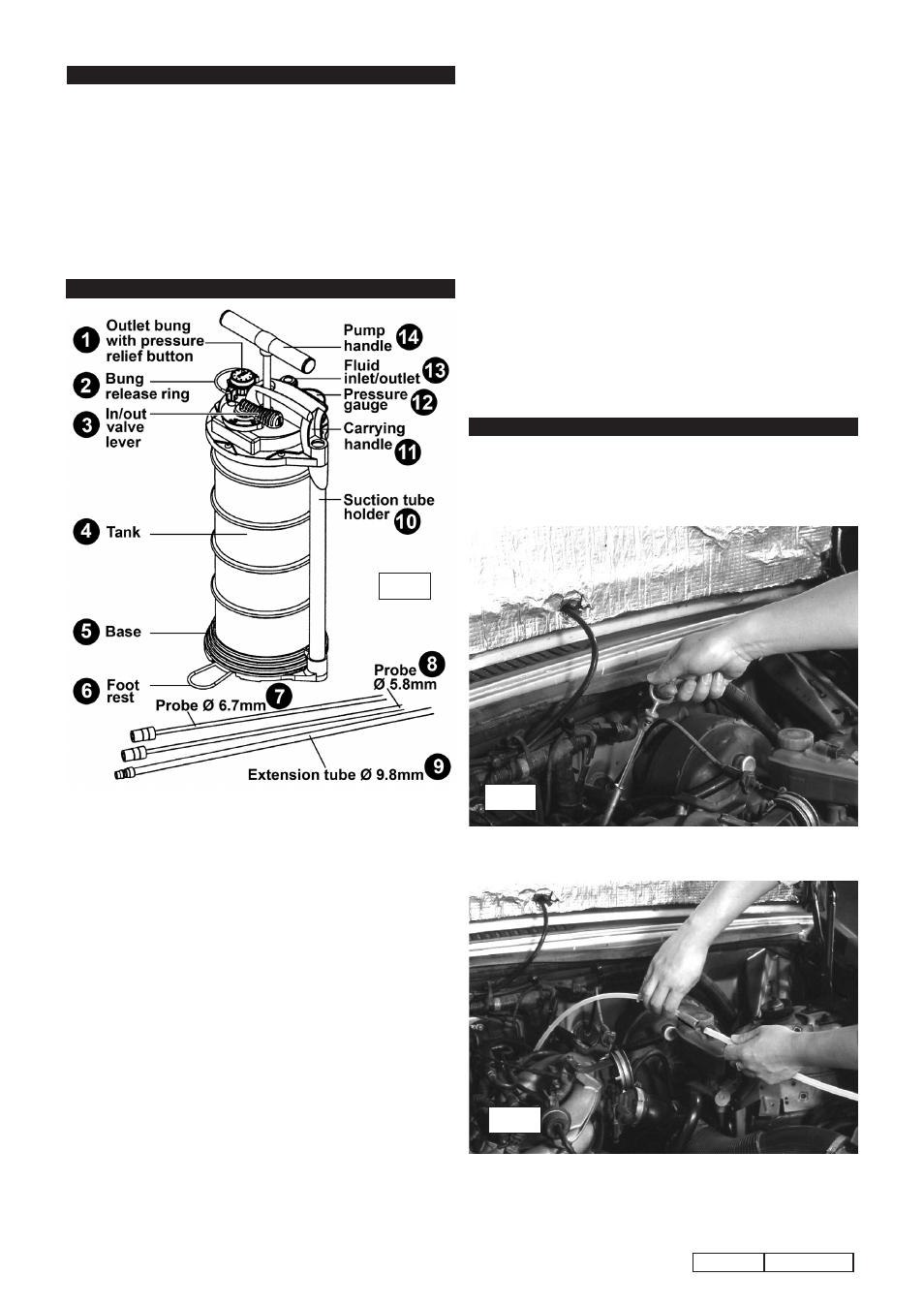
4. SET-UP FOR OIL CHANGE
Ensure you read, understand and apply the Section 1 Safety
Instructions.
4.1 first ensure that the vehicle is level. run the engine for
approximately five minutes to ensure that the oil is warm.
switch off engine.
4.2 remove the oil dipstick from the engine.
4.3 Insert the appropriate extracting probe into the dipstick tube
making sure it reaches the bottom of the sump. connect the
extracting probe to the extension tube using the black or red
soft plastic adaptor. the tubes are a push fit into the adaptor.
fig.4
fig.5
tP6905,tP6906
Issue no:1 17/10/08
3.8 Probe Ø5.8 this is the smaller of the two probes provided and
is intended for insertion into the dipstick tube of vehicles where
an oil change is required. the black plastic fitting on this tube is
a push fit onto the extension tube.
3.9 Extension tube Ø9.8 the fitting at one end of this tube fits
directly into the fluid inlet/outlet '13'. one of the probes will be
a push fit onto the other end of this tube.
3.10 Suction tube holder. the extension tube and the two probes
can be stored here when not required.
3.11 Carrying handle. the pump handle should be in the down
position to use the carrying handle.
3.12 Pressure gauge. the needle moves anti-clockwise from zero
when a vacuum is created to suck fluid into the tank. the
needle moves clockwise from zero when the tank is pressurised
to expell fluid from the tank. If the needle moves into the red
zone the excess pressure will be automatically released.
3.13 Fluid Inlet outlet. this fitting has a sliding sleeve which has to
be pulled downwards before the fitting on the end of the
extension tube will go in.
3.14 Pump handle. the pump handle should be moved up and
down through its full stroke for most efficient operation of the
pump. If the pump handle locks up this means the tank is full.
Press the pressure relief button to free the handle.
MAIN FEATURES OF EXTRACTOR UNITS
3.1 Outlet Bung. the outlet bung is inserted into a small spout in
the top of the unit which is used to manually empty oil out of
the tank. the bung has an integral pressure relief button built
into it. Press the button downwards into the bung and hold it
there until the pressure has equalised.
3.2 Bung Release Ring. to remove the bung take hold of the bung
release ring and turn the bung anti-clockwise until it stops. Pull
upwards to remove the bung. to lock the bung in place insert it
into the spout and turn it clockwise until it stops. the hooks on
either side of the bung should now be trapped under the
flanges on either side of the spout.
3.3 IN/OUT valve lever. When the valve lever is moved to the 'In'
position, operating the pump handle creates a vacuum, causing
fluid to be sucked into the tank via the probe/extension tube.
When the valve lever is moved to the 'out' position, operating
the pump handle pressurises the tank causing fluid to be
expelled from the tank.
3.4 Tank. After the unit has been used the tank should not be left in
either a vacuum or pressurised state. Push in the pressure
relief button and hold it down until the pressure has equalised.
3.5 Base. the base should be placed on a smooth level surface
during operation.
3.6 Footrest. When extra stability is required during pumping fold
out the footrest from underneath the base.
3.7 Probe Ø6.7 this is the larger of the two probes provided and
is intended for insertion into the dipstick tube of vehicles where
an oil change is required. the red plastic fitting on this tube is a
push fit onto the extension tube.
fig.3