Sealey SC02 User Manual
Page 2
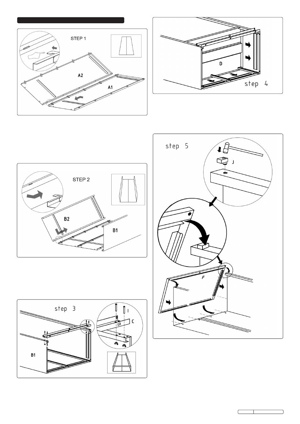
4. ASSEMBLY
4.5
TOP ASSEMBLY (Step 5)
4.5.1 Take the two top panel retainer mouldings (J) and fully
insert one into each hole at the top front edge of each
side panel in the orientation shown in Step 5.
4.5.2 Take the top panel (F) and hook it's front edge over the
two retainer mouldings, then swing the panel downwards
until the top edges of the back and side panels begin to
enter the receiving channels within the top panel. Tap the
top panel down into position using a rubber hammer until
the four indents in the back panels clip into the matching
holes in the back receiving channels.
4.4
BASE ASSEMBLY (Step 4)
4.4.1 Place the base (D) into position as shown above and
slide it down to the bottom until its edges make contact
with the receiving channels on the back and side panels.
Using a rubber hammer, tap the base down until it is fully
engaged in the channels.
4.3
CROSS MEMBER ASSEMBLY (Step 3)
4.3.1 Tie the side panels together at the bottom front edge by
attaching the cross member (C) using four bolts (I) and
four butterfly nuts as shown in the inset diagram above.
4.2
SIDE ASSEMBLY (Step 2)
4.2.1 Hold the side panels (B1 & B2) at a slight angle and fit
the tabs on the back panels into the slots of the side
panels and slide up to engage.
Original Language Version
4.1
BACK ASSEMBLY (Step 1)
4.1.1 Place the back panels (A1& A2) on a suitably protected
flat surface to prevent scratching.
4.1.2 Interlock the tabs into the slots on the back panels and
slide together until the two panels are fully engaged and
aligned.
SC02 Issue:1 - 15/07/10