Sealey AP6500 User Manual
Page 4
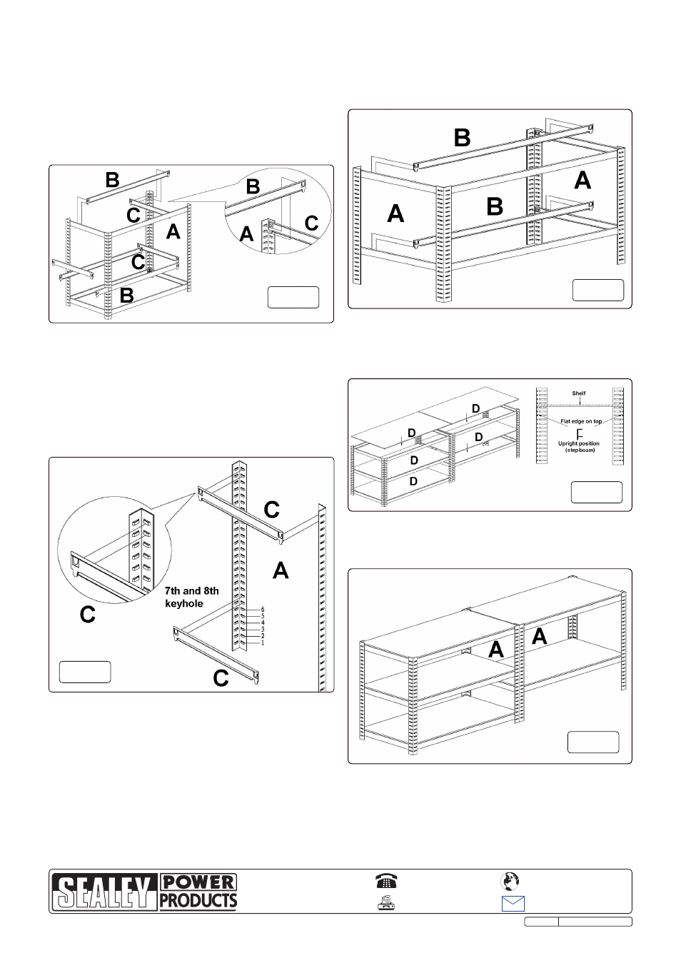
4.11 See Fig.13. now start to build the second low level unit by
making up two end frames as shown in Fig.13. one short
step beam (C) should be fixed at the top of the angle posts
and the other short step beam (C) should be fixed at the 7th
and 8th slots up from the bottom of the angle posts as
shown below. Ensure that each step beam is facing upwards.
Tap the beam at either end, close to each angle post to
ensure that the tabs are seated at the bottom of the slots.
4.12
See Fig.14. Join the two end frames together using the
four remaining long step beams as shown below. Ensure
that each step beam is facing upwards. Tap the beams at
either end, close to each angle post to ensure that the tabs
are seated at the bottom of the slots.
4.13 See Fig.15. Lay the shelves into position between the step
beams as shown above.
01284 757500
01284 703534
Sole UK Distributor
Sealey Group,
Bury St. Edmunds, Suffolk.
www.sealey.co.uk
Web
4.10 HALF HEIGHT WORKSTATION.
See Fig.12. Follow steps 4.2 and 4.3 to create a bottom frame
with four 'A' posts attached. using two long step beams (B)
and two short step beams (C) insert a shelf support level at
the top of the angle posts (A). Tap the beams at either end,
close to each angle post to ensure that the tabs are seated in
the slots. Insert another shelf support level at the desired height
within the frame using additional long and short step beams
and ensure that the tabs are seated in the slots.
Fig.12
Fig.13
Fig.15
Fig.14
Fig.16
AP6500 Issue: 1 - 05/06/09
4.14 See Fig.16. Place the two units end to end as shown below .